Table of Contents
Advertisement
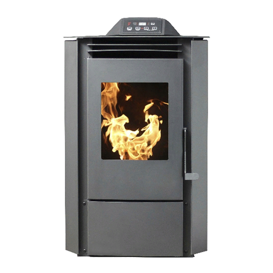
Owner's Operation and Instruction Manual
THIS MANUAL WILL HELP YOU TO OBTAIN EFFICIENT, DEPENDABLE SERVICE FROM THE HEATER, AND ENABLE YOU
TO ORDER REPAIR PARTS CORRECTLY. KEEP IN A SAFE PLACE FOR FUTURE REFERENCE.
• Read all instructions carefully before installing or
operating this stove. Failure to follow instructions may
result in property damage, bodily injury, or even death.
• Note: It is recommended installation be completed by
a qualified heating equipment installer!
• Refer to markings on stove labels for additional
information.
• Contact your local building or fire officials about
obtaining permits, restrictions, and installation
inspection requirements in your area.
• Safety Notice: If this stove is not properly installed, a
house/building fire may result. For your safety, contact
local or municipal building or fire officials about permits,
restrictions, and installation requirements for your area.
MODEL: AP5710
SAVE THESE INSTRUCTIONS
United States Stove Company
227 Industrial Park Road
P.O. Box 151
South Pittsburg, TN 37380
Report No. 0215PS052S
Certified to: ASTM E 1509-12, and Certified
to: ULC-S627-00, and (UM) 84-HUD
This unit is not intended to be used as a
primary source of heat.
U.S. Environmental Protection Agency
Certified to comply with 2015 particulate
emissions standards.
852523C-0301H
Advertisement
Table of Contents

Related Manuals for US Stove Company Ashley AP5710


Summary of Contents for US Stove Company Ashley AP5710
- Page 1 Owner’s Operation and Instruction Manual MODEL: AP5710 SAVE THESE INSTRUCTIONS THIS MANUAL WILL HELP YOU TO OBTAIN EFFICIENT, DEPENDABLE SERVICE FROM THE HEATER, AND ENABLE YOU TO ORDER REPAIR PARTS CORRECTLY. KEEP IN A SAFE PLACE FOR FUTURE REFERENCE. • Read all instructions carefully before installing or operating this stove.
-
Page 2: Safety Precautions
Safety Precautions This manual describes the installation and operation of the U.S. Stove, AP5710 wood heater. This heater meets the 2015 U.S. Environmental Protection Agency’s crib wood emission limits for wood heaters sold after May 15, 2015. Under specific test conditions this heater has been shown to deliver heat at rates ranging from 8,606 to 20,076 Btu/hr. -
Page 3: Specifications
Specifications Heating Specifications Fuel Burn Rate* (lowest setting) 1.5 lbs./hr. (0.7 kg/hr) Burn Time (lowest setting) 13 hrs. (approximate) Hopper Capacity 20 lbs. (9.1kg) Flue Size 3” or 4” * Pellet size may effect the actual rate of fuel feed and burn times. Fuel feed rates may vary by as much as 20%. Use PFI listed fuel for best results. -
Page 4: Installation Options
Installation INSTALLATION OPTIONS Read this entire manual before you install and use your pellet stove. Failure to follow instructions may result in property damage, bodily injury, or even death! (See specific installation details for clearances and other installation requirements) A Freestanding Unit—supported by pedestal/legs and placed on a non-combustible floor surface in compliance with clearance requirements for a freestanding stove installation. -
Page 5: Floor Protection
Installation FLOOR PROTECTION This heater must have a non-combustible floor protector (UL1618 ember protection) installed beneath it if the floor is of combustible material. US: Floor protector should be UL listed or equal too, needs to extend 6” to the front, 6” to each side, 1”... -
Page 6: Venting Requirements
Installation VENTING REQUIREMENTS • Install vent at clearances specified by the vent manufacturer. • Do not connect the pellet vent to a vent serving any other appliance or stove. • Do not install a flue damper in the exhaust venting system of this unit. The following installation guidelines must be followed to ensure conformity with both the safety listing of this stove and to local building codes. -
Page 7: Vent Termination Clearances
Installation VENT TERMINATION CLEARANCES A. Minimum 4-foot (1.22m) clearance below or beside any door or window that opens. Minimum 1-foot (0.3m) clearance above any door or window that opens. C. Minimum 3-foot (0.91m) clearance from any adjacent building. D. Minimum 7-foot (2.13m) clearance from any grade when adjacent to public walkways. Minimum 2-foot (0.61m) clearance above any grass, plants, or other combustible materials. - Page 8 Assembly Instructions STEP 1 Pull the factory installed wires out of the top of the stove. There will be two wire harnesses, as shown. STEP 2 Unpack the top mount controls and ensure that the wiring harness shown is attached securely. STEP 3 Connect the factory installed wiring harnesses to the control panel as shown.
-
Page 9: Through The Wall Installation
Installation THROUGH THE WALL INSTALLATION (RECOMMENDED INSTALLATION) Canadian installations must conform to CAN/CSA-B365. To vent the unit through the wall, connect the pipe adapter to the exhaust motor adapter. If the exhaust adapter is at least 18 in.(457mm) above ground level, a straight section of pellet vent pipe can be used through the wall. -
Page 10: Special Mobile Home Requirements
Installation OUTSIDE AIR SUPPLY (OPTIONAL, UNLESS INSTALLING IN A MOBILE HOME) Adequate ventilation air is required to operate this heater. During operation, the heater draws air for combustion which can be assisted by the installation of outside combustion air inlets. However, certain weather conditions such as icing or use of kitchen exhaust fans may impact and reduce the effectiveness of vents. -
Page 11: Control Panel
Control Panel PANEL CONTROLS The blowers and automatic fuel supply are controlled from a panel on the top of the unit. The control panel functions are a follows. A. ON/OFF SWITCH (“POWER” BUTTON) • When pushed, the stove will automatically ignite. No other fire starter is necessary. The igniter will stay on for at least 10 and up to 12 minutes, depending on when Proof of Fire is reached. -
Page 12: Operation
Operation • DO NOT USE CHEMICALS OR FLUIDS TO START THE FIRE - Never use gasoline, gasoline-type lantern fuel, kerosene, charcoal lighter fluid, or similar liquids to start or “freshen up” a fire in this stove. Keep all such liquids well away from the stove while it is in use. -
Page 13: Opening Door
Operation DAMPER CONTROL The damper control lever is located on the back of the stove on the lower left side. The damper adjusts the combustion air. This control is necessary due to the varied burn characteristics of individual installations, different pellet brands and pellet feed rates. -
Page 14: Interior Chambers
WARNING: FAILURE TO PROPERLY MAINTENANCE THE CLEAN OUTS WILL RESULT IN POOR PERFORMANCE OF THIS STOVE. INTERIOR CHAMBERS • Burn Pot: Periodically remove and clean the burn pot and the area inside the burn pot housing. In particular, it is advisable to clean out the holes in the burn pot to remove any build up that may prevent air from moving through the burn pot freely. -
Page 15: Maintenance
Maintenance DO NOT VACUUM HOT ASH • Failure to clean and maintain this unit as indicated can result in poor performance, safety hazards, fire, and even death. • Unplug your stove’s electrical cord prior to removing the back panel or opening the exhaust system for any inspection, cleaning, or maintenance work. -
Page 16: Maintenance Schedule
Maintenance BLOWER MOTORS Clean the air holes on the motors of both the exhaust and distribution blowers annually. Remove the exhaust blower from the exhaust duct and clean out the internal fan blades as part of your fall start-up. If you have indoor pets your power motors should be inspected monthly to make sure they are free of animal hair build up. -
Page 17: Troubleshooting Guide
Trouble Shooting Guide When your stove acts out of the ordinary, the first reaction is to call for help. This guide may save time and money by enabling you to solve simple problems yourself. Problems encountered are often the result of only five factors: 1) poor fuel;... - Page 18 Trouble Shooting Guide Display is Flashing “E2” Possible Causes Possible Remedies: (Unplug stove first when possible) Unhook air hose from the air switch and blow through it. Airflow switch hose or stove attachment If air flows freely, the hose and tube are fine. If air will not pipes for hose are blocked.
- Page 19 Trouble Shooting Guide Display is Flashing “E3” Possible Causes Possible Remedies: (Unplug stove first when possible) The hopper is out of pellets Refill the hopper. The air dampener is too far open for a low If on the low setting, you may need to close the feed setting dampener all the way.
- Page 20 Trouble Shooting Guide Display is Flashing “E4” Possible Causes Possible Remedies: (Unplug stove first when possible) The air inlet, burnpot, interior combustion air Follow all cleaning procedures in the maintenance chambers, combustion blower, or exhaust pipe section of the owner’s manual. are blocked with ash or foreign material.
- Page 21 Trouble Shooting Guide Stove Feeds Pellets, But Will Not Ignite Possible Causes Possible Remedies: (Unplug stove first when possible) Push the air damper in closer to the side of the stove for startup. In some situations it may be necessary to Air damper open too far for ignition.
- Page 22 Trouble Shooting Guide Stove Will Not Feed Pellets, But Fuel Feed Light Comes On As Designed Possible Causes Possible Remedies: (Unplug stove first when possible) Wait for the stove to cool for about 30 - 45 minutes. Locate the High Limit thermodisc and press the reset button on the High limit switch has tripped or is back of it.
- Page 23 Trouble Shooting Guide Glass “Soot’s” Up At A Very Fast Rate • Flame Is Lazy, Dark, And Has Black Tips • After Stove Has Been On For A While, The Burnpot Overfills • Possible Causes Possible Remedies: (Unplug stove first when possible) Stove or vent pipe is dirty, which restricts airflow Follow all cleaning procedure in the maintenance through the burnpot.
-
Page 24: Parts Diagram
Parts Diagram... -
Page 25: Parts List
Parts List Part No. Description Qty. 892199 Housing, PCBA Controller 80630 PCBA, Controller 891148 Lid Latch 892669 Top Weldment 80491 Lid Switch 80631 PCBA 892672 Vented Side Panel, Right 892673 Vented Side Panel, Left 892674 Vented Back Panel 892660 Hopper 80462 AC Electrical Connector 80602... -
Page 26: Parts Diagram / Parts List
Parts Diagram / Parts List Part No. Description Qty. 892663 Handle Assembly 40792 Feed Door 88066 3/4” Round Rope Gasket-Black 46 in 892667 Door Glass In order to maintain warranty, components must be replaced using original manufacturers parts purchased through your dealer or directly from the appliance manufacturer. -
Page 27: Wiring Diagram
Wiring Diagram... -
Page 28: Service Record
Service Record It is recommended that your heating system is serviced regularly and that the appropriate Service Interval Record is completed. Service Provider: Before completing the appropriate Service Record below, please ensure you have carried out the service as described in the manu- facturer’s instructions. - Page 29 Limited Warranty Pellet / Corn / Multi-Fuel Heaters (Inserts, Freestanding, and Pedestal) The operation of this heater in a manner inconsistent with the owner’s manual will void you warranty and is also against federal regulations. United States Stove Company warrants to the original purchaser its products against premature failure of any component due to workmanship, quality, or materials as follows: TIME PERIOD:...
- Page 30 Notes...
- Page 31 How To Order Repair Parts / Comment Commander Les Pièces De Rechange This manual will help you obtain efficient, dependable service from your pellet stove, and enable you to order repair parts correctly. Keep this manual in a safe place for future reference. When writing, always give the full model number which is on the nameplate attached to the heater.
Need help?
Do you have a question about the Ashley AP5710 and is the answer not in the manual?
Questions and answers