Table of Contents
Advertisement
Quick Links
French version is available for download from the U.S. Stove website: http://www.usstove.com/
Version française est disponible pour téléchargement à partir du site U.S. Stove: http://www.usstove.com
This unit is not intended to be used as a primary source of heat.
• Please read this entire manual before installation and use of this appliance. Failure to
follow these instructions could result in property damage, bodily injury, or even death.
• Contact your local building or fire officials about obtaining permits, restrictions and
installation inspection requirements in your area.
• Save these instructions.
OWNER'S MANUAL
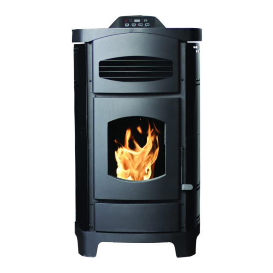
MODEL: AP5780
U.S. Stove Company
227 Industrial Park Road, South Pittsburg, TN 37380
Phone 800-750-2723 www.usstove.com
Report No. 0215PS061E
0215PS061S
Certified for installations in the
USA and Canada.
U.S. Environmental Protection Agency
Certified to comply with 2015 particulate
emissions standards.
852925-0804G
Advertisement
Table of Contents

Related Manuals for US Stove Company Ashley AP5780


Summary of Contents for US Stove Company Ashley AP5780
- Page 1 OWNER’S MANUAL MODEL: AP5780 Report No. 0215PS061E 0215PS061S Certified for installations in the USA and Canada. U.S. Environmental Protection Agency Certified to comply with 2015 particulate emissions standards. French version is available for download from the U.S. Stove website: http://www.usstove.com/ Version française est disponible pour téléchargement à partir du site U.S. Stove: http://www.usstove.com This unit is not intended to be used as a primary source of heat.
-
Page 2: Safety Precautions
Safety Precautions This manual describes the installation and operation of the Ashley, AP5780 wood heater. This heater meets the 2015 U.S. Environmental Protection Agency’s crib wood emission limits for wood heaters sold after May 15, 2015. Under specific test conditions this heater has been shown to deliver heat at rates ranging from 8,507 to 26,386 Btu/hr. This heater achieved a particulate emissions rate of 1.3g/hr when tested to method ASTM E2779-10 (*and an efficiency of 72%). • IMPORTANT: Read this entire manual before installing • Allow the stove to cool before performing any and operating this product. Failure to do so may maintenance or cleaning. Ashes must be disposed result in property damage, bodily injury, or even in a metal container with a tight fitting lid. The closed death. -
Page 3: Specifications
Specifications Heating Specifications Fuel Burn Rate* (lowest setting) 1.4lbs per hr Burn Time (lowest setting) 32 hrs Hopper Capacity 46lbs Flue Size 3“ or 4” (77mm to 102mm) * Pellet size may effect the actual rate of fuel feed and burn times. Fuel feed rates may vary by as much as 20%. Use PFI listed fuel for best results. Dimensions Height 37.16” (944mm) Width 20.81” (529mm) Depth 22.25” (566mm) Weight 162lbs Electrical Specifications Electrical Rating 120 Volts AC, 60 HZ, 3 Amps Watts (operational) 125W Watts (igniter running) 310W FUEL CONSIDERATIONS Your pellet stove is designed to burn premium hardwood pellets that comply with Association of Pellet Fuel Industries standards. (Minimum of 40 lbs density per cubic ft, 1/4” to 5/16” diameter, length no greater than 1.5”, not less than 8,200 BTU/lb, moisture under 8% by weight, ash under 1% by weight, and salt under 300 parts per million). Pellets that are soft, contain excessive amounts of loose sawdust, have been, or are wet, will result in... -
Page 4: Installation Options
Installation INSTALLATION OPTIONS Read this entire manual before you install and use your pellet stove. Failure to follow instructions may result in property damage, bodily injury, or even death! (See specific installation details for clearances and other installation requirements) A Freestanding Unit—supported by pedestal/legs and placed on a non-combustible floor surface in compliance with clearance requirements for a freestanding stove installation. Your pellet stove may be installed to code in either a conventional or mobile home (see SPECIAL MOBILE HOME REQUIREMENTS). The installation must comply with the Manufactured Home and Safety Standard (HUD), CFR3280, Part 24. -
Page 5: Floor Protection
Installation FLOOR PROTECTION This heater must have a non-combustible floor protector (UL1618 ember protection) installed beneath it if the floor is of combustible material. US: Floor protector should be UL listed or equal too, needs to extend 6” to the front, 6” to each side, 1” to the rear of the unit. Under and 2” beyond each side of the cleanout tee if an interior vertical instillation. Canada: Floor protector should comply with CAN/ULC standards. Needs to extend 18” to the front, 8” beyond each side of the unit. THROUGH THE WALL INTERIOR VERTICAL INSTALLATION INSTALLATION FLOOR PROTECTOR DIMENSIONS Back to Stove 1” (26mm) U.S. (8” (204mm) Can.) Side to Stove 6” (153mm) U.S. (8” (204mm) Can.) Front to Stove 6” (153mm) U.S. (18” (458mm)Can.) Back and Sides to Flue 6” (153mm) -
Page 6: Venting Requirements
Installation VENTING REQUIREMENTS • Install vent at clearances specified by the vent manufacturer. • Do not connect the pellet vent to a vent serving any other appliance or stove. • Do not install a flue damper in the exhaust venting system of this unit. • The following installation guidelines must be followed to ensure conformity with both the safety listing of this stove and to local building codes. -
Page 7: Vent Termination Clearances
Installation VENT TERMINATION CLEARANCES A. Minimum 4-foot (1.22m) clearance below or beside any door or window that opens. B. Minimum 1-foot (0.3m) clearance above any door or window that opens. C. Minimum 3-foot (0.91m) clearance from any adjacent building. D. Minimum 7-foot (2.13m) clearance from any grade when adjacent to public walkways. E. Minimum 2-foot (0.61m) clearance above any grass, plants, or other combustible materials. F. Minimum 3-foot (0.91m) clearance from an forced air intake of any appliance. G. Minimum 2-foot (0.61m) clearance below eves or overhang. H. Minimum 1-foot (0.3m) clearance horizontally from combustible wall. Must be a minimum of 3 foot (0.91m) above the roof and 2 foot (0.61m) above the highest point or the roof within 10 feet (3.05m). VENT TERMINATION CLEARANCES... - Page 8 Assembly Instructions Step 1 Pull the factory installed wires out of the top of the stove. There will be two wire harnesses, as shown. Step 2 Unpack the top mount controls and ensure that the wiring harness shown is attached securely. Step 3 Connect the factory installed wiring harnesses to the control panel as shown.
-
Page 9: Through The Roof/Ceiling Installation
Installation THROUGH THE WALL INSTALLATION (RECOMMENDED INSTALLATION) Canadian installations must conform to CAN/CSA-B365. To vent the unit through the wall, connect the pipe adapter to the exhaust motor adapter. If the exhaust adapter is at least 18 in.(457mm) above ground level, a straight section of pellet vent pipe can be used through the wall. Your heater dealer should be able to provide you with a kit that will handle most of this installation, which will include a wall thimble that will allow the proper clearance... -
Page 10: Special Mobile Home Requirements
Installation OUTSIDE AIR SUPPLY (OPTIONAL, UNLESS INSTALLING IN A MOBILE HOME) Adequate ventilation air is required to operate this heater. During operation, the heater draws air for combustion which can be assisted by the installation of outside combustion air inlets. However, certain weather conditions such as icing or use of kitchen exhaust fans may impact and reduce the effectiveness of vents. It is important to note that room air starvation will negatively impact the operation of the heater. Depending on your location and home construction, outside air may be necessary for optimal performance. -
Page 11: Control Panel
Control Panel PANEL CONTROLS The blowers and automatic fuel supply are controlled from a panel on the top of this unit. The control panel functions are a follows. A. ON/OFF SWITCH (“POWER” BUTTON) • When pushed, the stove will automatically ignite. No other fire starter is necessary. The igniter will stay on for at least 10 and up to 12 minutes, depending on when Proof of Fire is reached. The fire should start in approximately 5 minutes. • The red light located above the “POWER” button will turn green when pressed and remain green until the stove is turned off. • After pushing “POWER”, the auger motor is on for 3.5 minutes, off for 1 minute. During the remainder of the start-up period, the auger motor operates on the heat range “1” setting. -
Page 12: Operation
Operation • Do not use chemicals or fluids to start the fire - never use gasoline, gasoline-type lantern fuel, kerosene, charcoal lighter fluid, or similar liquids to start or “freshen up” a fire in this stove. Keep all such liquids well away from the stove while it is in use. • Hot while in operation. Keep children, clothing and furniture away. Contact may cause skin burns. This heater is designed to burn only PFI Premium grade pellets. This appliance can also burn pellets rated as standard after May 16, 2015. DO NOT BURN: 1. Garbage; 10. Salt water driftwood or other previously salt water 2. -
Page 13: Opening Door
Operation AUTOMATIC IGNITOR Fill hopper and clean burn pot. 1. Press “On/Off” button. Make sure green light comes on. 2. The damper should be completely closed or open no more than ¼ of the way during start-up. This will vary depending on your installation and elevation. Once fire is established adjust for desired flame increasing the amount the damper is open as the heat setting is increased. (See “DAMPER CONTROL”) 3. Adjust feed rate to desired setting by pressing “Heat Level Advance” button. If fire doesn’t start in 12 minutes, press “On/Off”, wait a few minutes, clear the burn pot, and start procedure again. DAMPER CONTROL The damper control lever is located on the back of the stove on the lower left side. -
Page 14: Shutdown Procedure
Operation / Maintenance SHUTDOWN PROCEDURE Turning your stove off is a matter of pressing the “POWER” button on the display board. The green light will turn back to red when the “POWER” button is pushed. The auger motor will stop, and the blowers will continue to operate until the internal firebox temperatures have fallen to a preset level. WARNING: Never shut down this unit by unplugging it from the power source. 1. Your stove is equipped with a high temperature thermodisc. This unit has a manual reset thermodisc. This safety switch has two functions. A. To recognize an overheat situation in the stove and shut down the fuel feed or auger system. B. In case of a malfunctioning convection blower, the high-temperature thermodisc will automatically shut down the auger, preventing the stove from overheating. -
Page 15: Maintenance
Maintenance INTERIOR CHAMBERS • Burn Pot: Periodically remove and clean the burn pot and the area inside the burn pot housing. In particular, it is advisable to clean out the holes in the burn pot to remove any build up that may prevent air from moving through the burn pot freely. • Heat Exchanger: There is a clean out plate on both sides of the heat exchanger that need to be removed to clean fly ash out of the heat exchanger. The cleanouts are located inside the cabinet doors, on the lower front corners of the heat exchanger. To access these clean outs, you must... -
Page 16: Spring Shutdown
Maintenance In the event you need to replace the glass, remove the four (4) screws and glass retainers. While wearing leather gloves (or any other gloves suitable for handling broken glass), carefully remove any loose pieces of glass from the door frame. Dispose of all broken glass properly. ONLY high temperature ceramic glass of the correct size and thickness may be used. DO NOT substitute alternative materials for the glass. Contact your authorized dealer to obtain this glass. Re-install the new glass by re-attaching the retainers and screws, be careful not to over tighten the screws for this could damage the glass. DO NOT abuse the door glass by striking, slamming or similar trauma. Do not operate the stove with the glass removed, cracked or broken. FALL START UP Prior to starting the first fire of the heating season, check the outside area around the exhaust and air intake systems for obstructions. Clean and remove any fly ash from the exhaust venting system. Clean any screens on the exhaust system and on the outside air intake pipe. Turn all of the controls on and make sure that they are... -
Page 17: Troubleshooting Guide
Trouble Shooting Guide When your stove acts out of the ordinary, the first reaction is to call for help. This guide may save time and money by enabling you to solve simple problems yourself. Problems encountered are often the result of only five factors: 1) poor fuel; 2) poor operation or maintenance; 3) poor installation; 4) component failure; 5) factory defect. You can usually solve those problems related to 1 and 2. Your dealer can solve problems relating to 3, 4 and 5. Refer to diagrams on page 25 to help locate indicated parts. For the sake of troubleshooting and using this guide to assist you, you should look at your heat level setting to see which light is flashing. • Disconnect the power cord before performing any maintenance! NOTE: Turning the ON/OFF Switch to ”OFF” does not disconnect all power to the electrical components of the stove. - Page 18 Trouble Shooting Guide Display is Flashing “E2” Possible Causes Possible Remedies: (Unplug stove first when possible) Unhook air hose from the air switch and blow through it. If air 1. Airflow switch hose or stove attachment pipes for flows freely, the hose and tube are fine. If air will not flow throw hose are blocked. the hose, use a wire coat hanger to clear the blockage. The air inlet, burnpot, interior combustion air Follow all cleaning procedures in the maintenance section of the chambers, combustion blower, or exhaust pipe owner’s manual.
- Page 19 Trouble Shooting Guide Display is Flashing “E3” Possible Causes Possible Remedies: (Unplug stove first when possible) 1. The hopper is out of pellets Refill the hopper. The air dampener is too far open for a low feed If on the low setting, you may need to close the dampener all the setting way.
- Page 20 Trouble Shooting Guide Display is Flashing “E4” Possible Causes Possible Remedies: (Unplug stove first when possible) 1. The air inlet, burnpot, interior combustion air Follow all cleaning procedures in the maintenance section of chambers, combustion blower, or exhaust pipe are the owner’s manual. blocked with ash or foreign material. The Proof of Fire (POF) thermodisc has came Check the (POF) thermodisc to see if the wires are connected unplugged properly. Temporarily bypass the POF thermodisc by disconnecting the two wires and connecting them with a short piece of wire. Then plug the stove back up.
- Page 21 Trouble Shooting Guide Stove Feeds Pellets, But Will Not Ignite Possible Causes Possible Remedies: (Unplug stove first when possible) Push the air damper in closer to the side of the stove for startup. In some situations it may be necessary to have the damper 1. Air damper open too far for ignition. completely closed for ignition to take place.
- Page 22 Trouble Shooting Guide Stove Will Not Feed Pellets, But Fuel Feed Light Comes On As Designed Possible Causes Possible Remedies: (Unplug stove first when possible) Wait for the stove to cool for about 30 - 45 minutes. Locate the High Limit thermodisc and press the reset button on the back of it. If the 1. High limit switch has tripped or is defective. heater will not restart, check the thermodisc to see if it’s bad. To test if the thermodisc is bad, you can bypass it as described previously for the POF thermodisc. Remove the auger motor from the auger shaft and try to run the unit. Bad Auger Motor.
- Page 23 Trouble Shooting Guide • Glass “Soot’s” Up At A Very Fast Rate • Flame Is Lazy, Dark, And Has Black Tips • After Stove Has Been On For A While, The Burnpot Overfills Possible Causes Possible Remedies: (Unplug stove first when possible) 1. Stove or vent pipe is dirty, which restricts airflow Follow all cleaning procedure in the maintenance section of through the burnpot. the owner’s manual. Check to make sure the vent pipe has been installed Vent pipe installed improperly. according to the criteria in the owner’s manual.
-
Page 24: Replacement Parts
Replacement Parts Vented Back Panel Auger Auger Bushing High Limit T-disc 892776 891132 892187 80455 Auger Motor Bracket Exhaust Blower Auger Motor Gasket, Exhaust Blower 892188 80488 80602 88166 Hopper Switch Vacuum Switch T-disc Exhaust 3 Prong Receptacle 80491 80599 80549 80462 In order to maintain warranty, components must be replaced using original manufacturers parts purchased through your dealer or directly from the appliance manufacturer. - Page 25 Replacement Parts Convection Blower Housing, PCBA Controller PCBA Hopper Handle 80709 80631 892199 891148 Top Assembly Ash Covers PCBA, Controller Ash Cover Gaskets 892771 80630 892770 88266 Front Louver Front Lower Plate Burn Pot Hair Pin 892774 892773 86624 83529 In order to maintain warranty, components must be replaced using original manufacturers parts purchased through your dealer or directly from the appliance manufacturer.
- Page 26 Replacement Parts Ignitor Power Cord Ignitor Tube Door Assy. 80607 80461 86633 892772 Door Glass Glass Gasket Door Handle Door 892775 88267 41“ 892663 892777 Door Gasket Side Panels - Set of 2, Gloss Black 88082 45“ 892764 Side Panels - Set of 2, Polished Stainless 892765 Side Panels - Set of 2,...
-
Page 27: Wiring Diagram
Wiring Diagram -27-... - Page 28 Notes...
-
Page 29: Service Provider
Service Record It is recommended that your heating system is serviced regularly and that the appropriate Service Interval Record is completed. SERVICE PROVIDER Before completing the appropriate Service Record below, please ensure you have carried out the service as described in the manufacturer’s instructions. Always use the manufacturer's specified spare part when replacement is necessary. - Page 30 Limited Warranty Pellet / Corn / Multi-Fuel Heaters (Inserts, Freestanding, and Pedestal) The operation of this heater in a manner inconsistent with the owner’s manual will void the warranty and is also against federal regulations. United States Stove Company warrants to the original purchaser its products against premature failure of any component due to workmanship, quality, or materials as follows: TIME PERIOD: Firebox / Firepot .........................
- Page 31 How To Order Repair Parts / Comment Commander Les Pièces De Rechange THIS MANUAL WILL HELP YOU OBTAIN EFFICIENT, DEPENDABLE SERVICE FROM YOUR PELLET STOVE, AND ENABLE YOU TO ORDER REPAIR PARTS CORRECTLY. KEEP THIS MANUAL IN A SAFE PLACE FOR FUTURE REFERENCE. WHEN WRITING, ALWAYS GIVE THE FULL MODEL NUMBER WHICH IS ON THE NAMEPLATE ATTACHED TO THE HEATER. WHEN ORDERING REPAIR PARTS, ALWAYS GIVE THE FOLLOWING INFORMATION AS SHOWN IN THIS LIST / CE GUIDE VOUS AIDERA A OBTENIR UN SERVICE EFFICACE ET FIABLE POUR CE POELE A GRANULES ET VOUS PERMETTRA DE COMMANDER CORRECTEMENT LES PIECES DE RECHANGE. VEUILLEZ CONSERVER CE GUIDE DANS UN ENDROIT SUR POUR VOUS Y REFERER. LORSQUE VOUS NOUS ÉCRIVEZ, VEUILLEZ INDIQUER LE NUMÉRO COMPLET DU MODÈLE AFFICHÉ SUR LA PLAQUE SIGNALÉTIQUE DE L’APPAREIL DE CHAUFFAGE. LORSQUE VOUS COMMANDEZ DES PIECES DE RECHANGE, VEUILLEZ TOUJOURS FOURNIR LES RENSEIGNEMENTS SUIVANTS QUI FIGURENT DANS CETTE NOMENCLATURE: 1. The part number / Le numero de reference de la piece ___________________ 2. The part description / La description de la piece __________________________ 3.
Need help?
Do you have a question about the Ashley AP5780 and is the answer not in the manual?
Questions and answers