Table of Contents
Advertisement
Quick Links
Download this manual
See also:
Service Manual
-( I.
R
IJ
"
~
~
~
l'
'"
-t
'"
o
<)
-~
Ii
L
D "" _'
OPERATORS MANUAL
5.SKW EDC 60HZ
5.0KW EDC 50HZ
MARINE DIES
GENERATORS
SECOND EDITION
DECEMBER 2007
WESTERBEKE CORPORATION -150 JOHN HANCOCK ROAD
MYLES STANDISH INDUSTRIAL PARK' TAUNTON
MA
02780
WEBSITE: WWW.WESTERBEKE.COM
---
§;JIH
Mmtber National Marine Manufacturers Association
Advertisement
Table of Contents
Troubleshooting

Related Manuals for Westerbeke 5.5KW EDC 60HZ


Summary of Contents for Westerbeke 5.5KW EDC 60HZ
- Page 1 '" <) D "" _' OPERATORS MANUAL 5.SKW EDC 60HZ 5.0KW EDC 50HZ MARINE DIES GENERATORS SECOND EDITION DECEMBER 2007 WESTERBEKE CORPORATION -150 JOHN HANCOCK ROAD MYLES STANDISH INDUSTRIAL PARK' TAUNTON 02780 WEBSITE: WWW.WESTERBEKE.COM §;JIH Mmtber National Marine Manufacturers Association...
- Page 2 WAR'NING Gene!ators Produce CARBON MONOXIDE Regular Maintenance Required IE[~!: A WARNING DECAL is provided by WESTERBEKE and should be fixed to bulkhead near your engine or generator. WESTERBEKE also recommends installing CARBON MONOXIDE DETECTORS near the engine room. They...
- Page 3 SAFETY INSTRUCTIONS PREVENT BURNS - FIRE INTRODUCTION Read this safety manual carefuUy. Most accidents are caused by failure to follow fundamental rules and WARNING: Fire can cause injury death! precautions. Know when dangerous conditions exist and take the necessary precautions to protect yourself, your •...
- Page 4 SAFETY INSTRUCTIONS ACCIDENTAL STARTING TOXIC EXHAUST GASES WARNING: Accidental starting can cause injury WARNING: Carbon monoxide (CO) is deadly gas! death! • Ensure that the exhaust system is adequate to expel gases • Disconnect the battery cables before servicing the engine! discharged from the engine.
- Page 5 SAFETY INSTRUCTIONS ABYC, NFPA AND USCG PUBLICATIONS FOR • Do not wear loose clothing or jewelry when servicing equipment; tie back long hair and avoid wearing loose INSTALLING DIESEL ENGINES jackets, shirts, sleeves, rings, necklaces or bracelets that Read the following ABYC, NFPA and USCG publications could be caught in moving parts.
- Page 6 INSTALLATION When installing WESTERBEKE engines and generators it is important that strict attention be paid to the following information: CODES AND REGULATIONS Strict federal regulations, ABYC guidelines, and safety codes must be complied with when installing engines and generators in a marine environment.
-
Page 7: Table Of Contents
TABLE OF CONTENTS Engine Adjustments (cont.) Parts Identification ..........Introduction ............Torquing the Cylinder Head Bolts ....23 Fuel, Engine Oil and Engine Coolant....5 Generator Frequency Adjustment....24 Preparations for Initial Start·Up ......Electronic Governor ........24 Digital Control PaneL ......... -
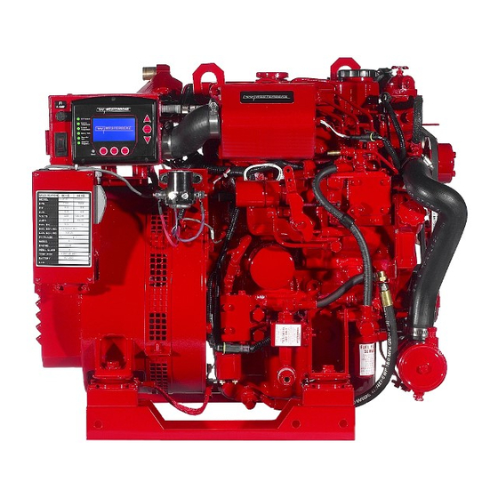
Page 8: Parts Identification
5.5KW GENERATOR PARTS IDENTIFICATION COOLANT PRESSURE INTAKE SILENCER REAR CIRCUIT --\-~~~~-r1r BREAKER -OIL DRAIN HOSE FUEL FILTER LIFT PUMP POWER TAKE-OFF CONNECTION RIGHT SIDE FLEXIBLE'/SOLATED MOUNTS ECU CONNECTION REMOTE PANEL CONNECTION ~'--- CONNECTION FOR SIPHON BREAK INJECTION ~~~~~§I THE"MOSTAT"-_ _ ASSEMBLY BELT-----M~' DRIVE... -
Page 9: Introduction
OF THE FURNISHING OR USE OF SUCH SOFTWARE. provided and a technical manual is available from your WESTERBEKE customers should also keep in mind the WESTERBEKE dealer. If you are planning to install this time span between printings of WESTERBEKE product equipment contact your WESTERBEKE dealer for software and the unavoidable existence of earlier WESTERBEKE'S installation manual. - Page 10 A carbon monoxide warning decal been provided SERIAL NUMBER LOCATION by WESTERBEKE. Affix this decal in a visible position in the The engine's model number and serial number areiocated on engine room. a nameplate mounted on the side of the engiae's manifold.
-
Page 11: Fuel, Engine Oil And Engine Coolant
DIESEL FUEL, ENGINE OIL AND ENGINE COOLANT DIESEL FUEL ENGINE COOLANT WESTERBEKE recommends a mixture of 50% antifreeze Use fuel that meets the requirements or specification of Class 2-D (ASTM), and has a cetane rating of #45 or better. and 50% distilled water. Distilled water is free from the chemicals that can corrode internal engine surfaces. -
Page 12: Preparations For Initial Start-Up
PREPARATIONS FOR INITIAL START-UP PREST ART INSPECTION Before starting your generator set for the first time or after a CAUTION: When starting the generator, it is prolonged layoff, check the following items: recommended that all AC loads, especially large motors, •... -
Page 13: Digital Control Panel
20 AMP DC CIRCUIT BREAKER (ECU) LIGHT DESCRIPTION r-----~.----, Battery Voltage Pressure WESTERBEKE'S Digital Control panel provides the 13.5 operator with an LCD display that continuously monitors all the operations of the generator in easy to understand text messages. SCROLL SCROLL... - Page 14 NMEA-2000 system or shut off the DC breaker on the generator's control box for a WESTERLlNK system. NOTE: Keep in mind that the Westerbeke generator maybe the DC power supply for the vessel's NMEA·2000 network.
-
Page 15: Generator Break-In Procedure
WESTERLINK system. When the engine is warm - almost Smokeless. When the engine is overloaded - some Black Smoke. . NOTE: Keep in mind that the Westerbeke generator maybe the DC power supply for the vessel's NMEA-2000 network. Engines Generators... -
Page 16: Maintenance Schedule (Chart)
MAINTENANCE SCHEDULE WARNING: Never attempt to pedorm any service while the engine Is running. Wear the proper safety equipment such as goggles and gloves, and use the cDaeet tDols fDr each job. /)iscDnnect the battery terminals when servicing any Df the engine's DC electrical equipment. NOTE: Many of the following maintenance jobs are simple but others are more difficult and may require the expert knowledge of a service mechanic. - Page 17 Adjust Valve Clearances (see ENGINE ADJUSTMENTS). *Heat Exchanger Remove, have professionally cleaned and pressure tested. *WESTERBEKE recommends this service be performed by an authorized mechanic. NOTE: WHEN SERVICING/CHANGING DC COMPONENTS. THE DC POWER MUST BE TURNED OFF USING EITHER THE BREAKER OR THE BATTERY SWITCH.
-
Page 18: Fuel System
This process is accomplished by installing and maintaining a proper fuel filter/water separator between the fuel tank and the generator/engine. Westerbeke recommends a 10 micron filter be used. FUEL INJECTION PUMP The fuel injection pump is the most important component of the diesel engine, requiring the utmost caution in handling. -
Page 19: Cooling System
DESCRIPTION fresh water coolant flows around the tubes; engine heat trans- Westerbeke marine diesel engines are designed and equipped ferred to the fresh water coolant is conducted through the for fresh water cooling. Heat produced in the engine by com-... -
Page 20: Fresh Water Cooling Circuil
COOLING SYSTEM CHANGING COOLANT FRESH WATER CODLING CIRCUIT The engine's coolant must be changed according to the NOTE: Refer to the ENGINE COOLANT section for the rec- MAINTENANCE SCHEDULE. If the coolant is allowed to ommended antifreeze and water mixture be used as the become contaminated, it can lead to overheating problems. -
Page 21: Thermostat
COOLING SYSTEM THERMOSTAT RAW WATER INTAKE STRAINER A thennostat, located near the manifold at the front of the NOTE: Always install the strainer at or below the waterline so engine, controls the coolant temperature as the coolant the strainer will always be selfpiiming. continuously flows through the closed cooling circuit When A clean raw water intake strainer is a vital component of the is first... -
Page 22: Raw Water Cooling Circuit
COOLING SYSTEM RAW WATER PUMP RAW WATER COOLING CIRCUIT The raw water pump is a self-priming, rotary pump with a The raw water flow is created by a positive displacement non-ferrous housing and a Neoprene impeller. The impeller impeller pump. This pump draws water directly from the fie~ble blades which wipe against a curved cam plate ocean, lake, or river from a thru-hull opening through a hose... -
Page 23: Engine Lubricating Oil
ENGINE LUBRICATING OIL ENGINE OIL CHANGE When installing the new oil filter element, wipe the filter gasket's sealing surface on the bracket free of oil and 1. Draining the Oil Sump. Discharge the used oil through of clean apply a thin coat engine oil the rubber gasket the sump dram hose (attached to the front of the engine) -
Page 24: Remote Oil Filter (Optional)
REMOTE OIL FILTER (OPTIONAL) REMOTE OIL FILTER KIT PN#040078 INSTALLATION NOTE: Westerbeke is responsible for engine failure due to incorrect installation the Remote Oil Filter. J'his popular accessory is used to relocate the engine's oil fil- ter from the engine to a more convenient location such as an ~ngine room bulkhead. -
Page 25: Starter Motor
STARTER MOTOR DESCRIPTION The starter is a new type, small, light-weight and is called a SOLENOID " high-speed internal-reduction starter. The pinion shaft is separate from the motor shaft; the pinion slides only on the pinion shaft. A reduction gear is installed between the motor shaft and a pinion shaft. - Page 26 STARTER MOTOR EMERGENCY START WARNING: When performing these procedures! Corrosion to the starter brushes and/or the solenoid contacts position yourself safely away from the moving parts of can cause the sporadic problem of the engine starting one time but not another. If corrosion is the problem, the starter the engine in case the engine starts-up.
-
Page 27: Generator Specifications
SPECIFICATIONS· 5.5KW EDC GENERATOR ELECTRICAL SYSTEM ENGINE SPECIFICATIONS Engine Type Diesel, four-cycle, four-cylinder, fresh Starting Battery 12-Volt, (-) negative ground water-cooled, vertical in-line overhead valve Battery Capacity 800-1000 Cold Cranking Amps (CCA) mechanism (11 Hp at 1800 rpm maximum). DC Charging Alternator... -
Page 28: Wiring Diagram #'52441
WIRING DIAGRAM #52414 iIl - 1,L- • I... -
Page 29: Engine Adjustments
ENGINE ADJUSTMENTS NOTE: WESTERBEKE recommends that the following engine adjust- ments be performed a competent engine mechanic. The information below is provived to assist the mechanic. TORQUING THE CYLINDER HEAD BOLTS DRIVE BELT ADJUSTMENT For your safety, WESTERBEKE generator models come... -
Page 30: Generator Frequency Adjustment
ON THE CONTROL PANEL f C U ' BOARD MUST BE SWITCHED: SWITCHES ON FOR 50 HZ AND OFF FOR 60 HZ. 1-+----13/16"TO 7/8" STANDARD NOTE: For additional infomwtion Electronic Governor Troubleshooting,rejer to your WESTERBEKE Service Manual. Ehgines & Generators... -
Page 31: Valve Clearance Adjustment
ENGINE ADJUSTMENTS VALVE CLEARANCE ADJUSTMENT Re-install the glow plugs (use anti-seize compound on the threads) and assemble the rocker cover and rocker cover NOTE: Retorque the cylinder head bolts before adjusting the TIGHTENING bolts. See TORQUE SCHEDULE in this engine's valves. See HEAD TORQUING CYLINDER... -
Page 32: Spill Timing
ENGINE ADJUSTMENTS NOTE: WESTERBEKE recommends that the following engine adjust- ments be performed by a competent engine mechanic. infonnation below is provided to assist the mechanic. Injection Pump Timing Adjustment (Spill Timing) INJECTION PUMP If your engine's fuel injection timing is not properly adjusted,... -
Page 33: Testing Glow Plugs
ENGINE ADJUSTMENTS NOTE: WESTERBEKE recommends the following engine adjust- that ments be performed by a competent engine mechanic. The infonnation below is provided to assist mechanic. TESTING GLOW PLUGS OIL PRESSURE The engine's oil pressure,is constantly monitored by the control To inspect the plug, remove the electrical terminal connec- panel. -
Page 34: Fuel Injectors
FUEL INJECTORS Inspecting Spray Pattern REMOVING THE INJECTORS Operate the hand lever of the nozzle tester at intervals of NOTE: Injector must be serviced in a "clean room" environment. one stroke per second to check if the fuel is injected cor- 1. -
Page 35: Engine Troubleshooting (Chart)
ENGINE TROUBLESHOOTING The following troubleshooting table describes certain NOTE: The engine's DC electrical system is protected by a problems relating to engine service, the probable causes of 20 amp rocker type manual reset circuit breaker mounted the problems, and the recommendations to overcome these on the generator's control box next to the LCD Display problems. - Page 36 ENGINE TROUBLESHOOTING Problem Probable Cause Verification/Remedy Incorrect grade of engine oil. Exhaust smoking problems Blue smoke. 1a. Crankcase is overfilled with engine oil (oil is blowing out through the eXhaust). 2. Engine is running cold. 2. White smoke. 2a. Faulty injector or incorrect injector timing. 3.
-
Page 37: Alternator Testing
WARNING: A working alternator runs hot. A failed The following infonnation applies to the standard alternators alternator can become very hot. Do not touch the that are/supplied with WESTERBEKE'S Engines and Generators. altemator until if has cooled. ELECTRICAL CHARGING CIRCUIT... - Page 38 ALTERNATORS TESTING/TROUBLESHOOTING MEASURING BATTERY VOLTAGE TESTING THE ALTERNATOR ENGINE OFF) CAUTION: Before starting the engine make certain that everyone is clear of moving parts! Keep test away from sheaves and belts during procedures. ~tart the Engine. 2. After the engine has run for a few minutes, measure the starting battery voltage the battery tenninals using a multimeter set on DC volts.
-
Page 39: Battery Care
If tests indicate a failed alternator, it will need to be disas- sembled and repaired. good alternator service shop can do the job. NOTE: WESTERBEKE'S Service Manual detailed instructions for the disassembly and repair of their standard altematoTs. BATTERY CARE The minimum recommended capacity of the battery used in 3. -
Page 40: Shore Power Connections
.------.' < 1 J ' WESTERBEKE dealer. / - ~ k \ + - - ~ N E = = U T ; ' ; : ' : ~ ' : : ' : - : : : : " L rJ·;... -
Page 41: Generator Information
GENERATOR INFORMATION USE OF ELECTRIC MOTORS Generator Frequency Adjustment Frequency is a direct result of engine/generator speed, as The power required to start an electric motor is considerably more than is required to keep it running after it is started. indicated the following: Some motors require much more current to start them than... -
Page 42: Generator Single Phase
This mutual buildup of NOTE: This circuit breaker is available as a WESTERBEKE voltage in the four rotating poles and in the exciter windings add-on kit for earlier model generators; contact your quickly reaches the saturation point of the capacitor(s) and a WESTERBEKE dealer. -
Page 43: No Load Voltage Adjustment
WESTERBEKE BC Genetator Troubleshooting Guide). WARNING:... -
Page 44: Dual Exciter Model
BC GENERATOR SINGLE PHASE NOTE: WESTERBEKE recommends that the following generator tests and adjustments be performed by a qualified technician. DUAL EXCITER CIRCUIT MODEL NOTE: When changing Hertz. produced the generator, an engine speed change must be made. This is done the ECU. -
Page 45: Bridge Rectifier
Before attempting any repairs, get a clear an explanation of between cause and effect is understood. the problem as possible, preferably from an individual WESTERBEKE recommends that the troubleshooting and witnessing the problem. some cases, this may bring to repair of the generator be performed by a qualified technician... - Page 46 (12 months or more) The reco!:· . ssioning of your Westerbeke engine after a WEs1ERBEKE recommends removing the fuel injectors for seasonalla -up generally follows the same procedures as access to the cylinders. Squirt light lubricating oil into the...
-
Page 47: Lay-Up And Recommissioning
LAY-UP & RECOMMISSIONING GENERAL Fuel System [Gasoline Many owners rely on their boatyards to prepare their craft, Top off your fuel tanks with unleaded gasoline of 89 octane including engines and generators, for lay-up during the or higher. A fuel conditioner such as Sta-Bil gasoline off-season or for long periods of inactivity. -
Page 48: Power Take Off
The 5.0Kw BCD produces 9.2hp at a continuous 1800 rpm. This horsepower can be utilized either for generator AC output or to operate the power take off. Contact your WESTERBEKE DISTRIBUTOR/or additional in/ormation. REMOVE COVER POWER TAKE OFF... -
Page 49: Metric Conversion Data (Chart)
DECIMAL TO METRIC EQUIVALENT CHART Fractions of Fractions of Decimal (in.) Metric (mm) Decimal (in.) Metric (mm) an inch an inch 0.515625 13.09687 1/64 0.015625 0.39688 33/64 13.49375 0.53125 0.03125 0.79375 17/32 1/32 0.046875 1.19062 0.546875 13.89062 3/64 35/64 14.28750 0.0625 1.58750 9/16... - Page 50 STANDARD AND METRIC CONVERSION DATA LENGTH-DISTANCE Inches (in) x 25.4 Millimeters (mm) x .0394 Inches Feet (ft) x .305 = Meters (m) x 3.281 = Feet Miles x 1.609 Kilometers (km) x .0621 = Miles DISTANCE EQUIVALENTS 1 Degree of Latitude = 60 Nm = 111.120 km 1 Minute of Latitude = 1 Nm = 1.852 km VOLUME Cubic Inches (in3) x 16.387 = Cubic Centimeters x .061 =in...
-
Page 51: Sugges,Ed Spares
SUGGESTED SPARE PARTS CONTACT YOUR WESTERBEKE DEALER FOR SUGGESTIONS AND ADDITIONAL INFORMATION WESTERBEKE RECOMMENDS CARRYING ENOUGH ENGINE OIL (YOUR BRAND) FOR AN OIL CHANGE AND A GALLON OF PREMIXED COOLANT: SPARE DRIVE BELTS FUEL SYSTEM· HARDWARE KIT MOLDED IN-LINE HOSE KIT... - Page 52 & Engines Generators 1l15wmdwlW&...
Need help?
Do you have a question about the 5.5KW EDC 60HZ and is the answer not in the manual?
Questions and answers