Table of Contents
Advertisement
Quick Links
Advertisement
Table of Contents

Related Manuals for MSI 945GC Network


Summary of Contents for MSI 945GC Network
- Page 1 945GC Network MS-96C4 (V1.X) Server Board G52-96C41X1...
-
Page 2: Trademarks
If a problem arises with your system and no solution can be obtained from the user’s manual, please contact your place of purchase or local distributor. Alternatively, please try the following help resources for further guidance. Vis i t the MSI webs ite at http ://glob al.msi. com.tw /index. php? func=service for FAQ, technical guide, BIOS updates, driver updates, and other information. -
Page 3: Safety Instructions
Safety Instructions Always read the safety instructions carefully. Keep this User’s Manual for future reference. Keep this equipment away from humidity. Lay this equipment on a reliable flat surface before setting it up. The openings on the enclosure are for air convection hence protects the equip- ment from overheating. -
Page 4: Fcc-B Radio Frequency Interference Statement
FCC-B Radio Frequency Interference Statement T h is eq uip men t h as been tested and found to c omply with the limits for a Class B digital device, pursuant to Part 15 of the FCC Rules. These limits are designed to provide reasonable protection against harmful interference in a residential installation. -
Page 5: Weee (Waste Electrical And Electronic Equipment) Statement
WEEE (Waste Electrical and Electronic Equipment) Statement... -
Page 8: Table Of Contents
CONTENTS Copyright Notice ......................ii Trademarks ........................ii Revision History ......................ii Technical Support ......................ii Safety Instructions ......................iii FCC-B Radio Frequency Interference Statement ............iv W EEE (Waste Electrical and Electronic Equipment) Statement ........v Chapter 1 Getting Started ..................1-1 Mainboard Specifications ................... -
Page 9: Chapter 1 Getting Started
Getting Started Chapter 1 Getting Started Thank you for choosing the 945GC Network (MS-96C4 V1.X), an excellent server board from MSI. ® Based on the innovative Intel 945GC & ICH7 chipsets for optimal system efficiency, the 945GC Network ac- ®... -
Page 10: Mainboard Specifications
M S-96C4 Server Board Mainboard Specifications Proce ssor - I nt el A t om p roc es sor, si ngl e-c ore (230 ) & d ual -c ore (3 30) (Diam ondville) - 533MHz Chipset - Northbridge: Intel 945GC chipset - Southbridge: Intel ICH7 chipset M e mo r y - 2 unbuffered non-ECC DDR2 400/533 DIMM slots (240pin/1.8V) - Page 11 Getting Started Onboard I/O Front I/O - 1 DB9 serial port - 2 USB 2.0 ports - 4 RJ-45 Gigabit LAN jacks Onboard Connectors - 1 USB 2.0 pinheader (2 ports) - 1 serial port pinheader - 1 DB15 VGA connector - 1 TPM pinheader - 1 SPI Flash ROM pinheader (for debugging) Slot...
-
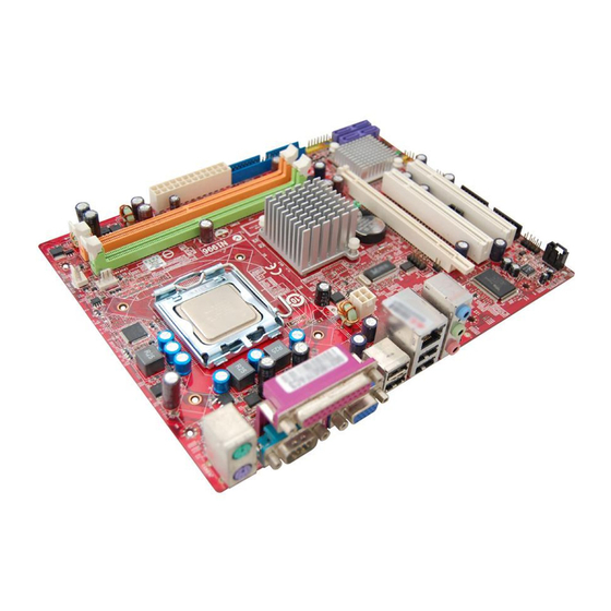
Page 12: Mainboard Layout
JP W1 Intel Intel J LA N4 Diam ondville ICH7 J P1 ID E1 JP 2 J SP I1 SATA1 JTP M1 SATA3 PC I_E 1 C PU FAN1 JFP 1 F_U S B1 945GC Network (MS-96C4 V1.X) Server Board... -
Page 13: Watch Dog Timer Setting
Getting Started Watch Dog Timer Setting MS-96C4 watchdog timer is using Super I/O Winbond W83627EHG. Setup procedures A. Enter super I/O configuration mode - dx, 04eh al, 087h dx, al dx, al B. Set pin 77 to W DTO# function dx,04eh al,02Dh;;... - Page 14 M S-96C4 Server Board dx, 04eh ;CR 30h: bit 0 fill in 1 al, 030h dx, al al, 01h dx, al ; Setup WDTO# count mode ; Set bit 4 and bit 3 by request ; Set bit 2 to 0 ;...
- Page 15 Getting Started dx, 04eh ;CR F7h: bit 4 fill 0 (clear event) al, 0f7h dx, al al,dx al, 0efh dx, al ;CR F6h: bit0~7 fill in counter time E. Exit configuration mode dx, 04eh al, 0aah dx, al...
- Page 16 M S-96C4 Server Board...
-
Page 17: Chapter 2 Hardware Setup
Hardware Setup Chapter 2 Hardware Setup This chapter provides you with the information about hardware setup procedures. While doing the installation, be careful in holding the components and follow the installation procedures. For some components, if you install in the wrong orientation, the components will not work properly. -
Page 18: Quick Components Guide
M S-96C4 Server Board Quick Components Guide JVGA1, p.2-12 AUXFAN1, p.2-11 COM2, p.2-11 DIMM Slots, p.2-3 Front Panel I/O, p.2-5 SYSFAN1, p.2-11 ATX1, p.2-4 MINIPCI1, p.2-17 CF1, p.2-18 JPW1, p.2-4 SATA1, SATA3, JPW1 p.2-10 JP1, p.2-15 JSPI1, p.2-10 JBAT1, p.2-16 JP2, p.2-15 J3, p.2-13 J4, p.2-18... -
Page 19: Memory
Hardware Setup Memory These DIMM slots are intended for system memory modules. DDR2 240-pin, 1.8V 64x2=128 pin 56x2=112 pin Installing Memory Modules 1. Locate the DIMM slots on the mainboard. Flip open the retaining clip at each side of the DIMM slot. 2. -
Page 20: Power Supply
M S-96C4 Server Board Power Supply System Power Connector: ATX1 This connector allows you to connect a 24-pin power supply. To pin 12 connect the 24-pin power supply, make sure the power supply connector is inserted in the proper orientation and the pins are aligned. -
Page 21: Front Panel I/O
Hardware Setup Front Panel I/O LAN1 LAN2 LAN3 LAN4 Serial Port USB Ports GbE LAN GbE LAN GbE LAN GbE LAN (LAN Bypass) (LAN Bypass) LAN Bypass Enable LAN Bypass Disable Serial Port The serial port is a 16550A high speed communications port that sends/ receives 16 bytes FIFOs. - Page 22 M S-96C4 Server Board LAN Bypass Definition Bypass setting in BIOS Power BIOS Bypass Setting Bypass Behavior Status Disable Bypass mode after power on Enable Bypass mode after power off Disable (All segment or by each segment are controllable) Enable Pass Through Behavior: A Bypass Behavior: B...
- Page 23 Hardware Setup Programming Guide LPC I/O address: 5E Power ON/OFF State Bypass Control Status Register Set/Read bypass mode Default Value: 0xD0 (Base on Customer Demand) Power ON/OFF State Bypass Control Status Register I/O Address: 5E Segment 4 Segment 3 Segment 2 Segment 1 Used Used...
- Page 24 M S-96C4 Server Board Sample code to access IO Port 5Eh IO Port 5Eh High Bit 0/1 POWER ON LAN 1-2 Bypass POWER ON LAN 1-2 Pass Through Bit 2/3 POWER OFF LAN 1-2 Bypass POWER OFF LAN 1-2 Pass Through Set Bit 0 and 1 to High dx, 5Eh al, dx...
-
Page 25: Connector
Hardware Setup Connector IDE Connector: IDE1 This connector supports IDE hard disk drives, optical disk drives and other IDE devices. IDE1 Important If you install two IDE devices on the same cable, you must configure the drives separately to master / slave mode by setting jumpers. Refer to IDE device’s documentation supplied by the vendors for jumper setting instructions. - Page 26 M S-96C4 Server Board SPI Flash ROM Pinheader: JSPI1 This pinheader is used to flash SPI flash ROM. Pin Definition Description Description JSPI1 VCC3_SB VCC3_SB SPI_MISO_F SPI_MOSI_F SPI_CS0_F# SPI_CLK_F SPI_HOLD# Serial ATA Connector: SATA1, SATA3 This connector is a high-speed Serial ATA interface port. Each connector can con- nect to one Serial ATA device.
- Page 27 Hardware Setup Serial Port Connector: COM2 This connector is a 16550A high speed communications port that sends/receives 16 bytes FIFOs. You can attach a serial device to it through the optional serial port bracket. Pin Definition SIGNAL DESCRIPTION Data Carry Detect Serial In or Receive Data SOUT Serial Out or Transmit Data...
- Page 28 M S-96C4 Server Board VGA Connector: JVGA1 The DB15-pin female connector is provided for monitor. Front USB Pinheader: F_USB1 ® This pinheader, compliant with Intel I/O Connectivity Design Guide, is ideal for con- necting high-speed USB interface peripherals such as USB HDD, digital cameras, M P3 players, printers, modems and the like.
- Page 29 Hardware Setup I2C Bus Connector: J3 This connector, known as I C, is for users to connect System Management Bus (SMBus) interface. Pin Definition SIGNAL VCC5V SMBus_Clock SMBus_Data +12V Power Button Front Panel Connector: JFP1 This connector is for electrical connection to the front panel switches and LEDs and ®...
- Page 30 M S-96C4 Server Board Keyboard/Mouse Pinheader: J0 This pinheader is used to connect a mouse/keyboard. Pin Definition SIGNAL KBMS_Power KBMS_Power MSCLK KBCLK MSDAT KBDAT TPM Pinheader: JTPM1 (Optional) This pinheader connects to an optional TPM (Trusted Platform Module). Please refer to the TPM security platform manual for more details.
- Page 31 Hardware Setup CPLD Data Reflash Pinheader: JP1, JP2 JP1 / JP2 Pin Definition Description Description IspEN TRST 2-15...
-
Page 32: Jumper
M S-96C4 Server Board Jumper Clear CMOS Jumper: JBAT1 There is a CMOS RAM onboard that has a power supply from an external battery to keep the data of system configuration. W ith the CMOS RAM, the system can auto- matically boot OS every time it is turned on. -
Page 33: Slot
Hardware Setup Slot Mini PCI Slot Important When adding or removing expansion cards, make sure that you unplug the power supply first. Meanwhile, read the documentation for the expansion card to configure any necessary hardware or software settings for the expan- sion card, such as jumpers, switches or BIOS configuration. - Page 34 M S-96C4 Server Board CompactFlash Card Slot: CF1 (Optional) This CompactFlash slot shares one channel of the IDE controller (CF => Master; IDE => Slave). You can install one CompactFlash typeI / type II device. CF Mode Jumper: J6 This jumper is used to select Master/Slave mode of the CF device. Master Slave CF Voltage Jumper: J4...
-
Page 35: Chapter 3 Bios Setup
BIOS Setup Chapter 3 BIOS Setup This chapter provides information on the BIOS Setup program and allows you to configure the system for optimum use. You may need to run the Setup program when: ² An error message appears on the screen during the system booting up, and requests you to run SETUP. -
Page 36: Entering Setup
M S-96C4 Server Board Entering Setup Power on the computer and the system will start POST (Power On Self Test) process. W hen the message below appears on the screen, press <Del> key to enter Setup. Press Del to enter SETUP If the message disappears before you respond and you still wish to enter Setup, restart the system by turning it OFF and On or pressing the RESET button. -
Page 37: Control Keys
BIOS Setup Control Keys < > Move to the previous item < > Move to the next item < > Move to the item in the left hand < > Move to the item in the right hand <Enter> Select the item <Esc>... -
Page 38: The Menu Bar
M S-96C4 Server Board The Menu Bar Main Use this menu for basic system configurations, such as time, date etc. Advanced Use this menu to set up the items of special enhanced features. Boot Use this menu to specify the priority of boot devices. Security Use this menu to set supervisor and user passwords. -
Page 39: Main
BIOS Setup Main System BIOS Information, Processor, System M emory These items show the firmware and hardware specifications of your system. Read only. System Time This setting allows you to set the system time. The time format is <Hour> <Minute> <Second>. -
Page 40: Advanced
M S-96C4 Server Board Advanced CPU Configuration... - Page 41 BIOS Setup Hyper-Threading Technology The processor uses Hyper-Threading technology to increase transaction rates and reduces end-user response times. The technology treats the two cores inside the processor as two logical processors that can execute instructions simultaneously. In this way, the system performance is highly improved. If you disable the function, the processor will use only one core to execute the instructions.
- Page 42 M S-96C4 Server Board [LBA/Large Mode] Enabling LBA causes Logical Block Ad- dressing to be used in place of Cylinders, Heads and Sectors [Block(Multi-Sector Transfer)] Any selection except Disabled determines the number of sectors transferred per block [PIO Mode] Indicates the type of PIO (Programmed Input/ Output) [DMA Mode] Indicates the type of Ultra DMA...
- Page 43 BIOS Setup Hardware Health Configuration These items display the current status of all of the monitored hardware devices/ components such as voltages, temperatures and all fans’ speeds. SYSFAN Mode Setting, CPUFAN Mode Setting, AUXFAN Mode Setting This item enables or disables the Smart Fan feature. Smart Fan is an excellent feature which will adjust the CPU/system fan speed automatically depending on the current CPU temperature to prevent your system from overheating.
- Page 44 M S-96C4 Server Board [Thermal Cruise M ode] SYSFAN TargetTemp Value, CPUFAN TargetTemp Value, AUXFAN TargetTemp Value Select a temperature setting here, and if the temperature of the CPU climbs up to the selected temperature setting, the system will automatically in- crease the speed of the CPU/system fan to cool down the overheated CPU.
- Page 45 BIOS Setup ACPI Configuration Advanced ACPI Configuration ACPI Version Features This item specifies the ACPI version. 3-11...
- Page 46 M S-96C4 Server Board Chipset ACPI Configuration APIC ACPI SCI IRQ This setting allows you to enable or disable the internal I/O APIC and Multipro- cessor Tables. High Performance Event Timer The High Precision Event Timer (HPET) was developed jointly by Intel and Microsoft to meet the timing requirements of multimedia and other time-sensitive applications.
- Page 47 BIOS Setup APM Configuration Resume On LAN This field specifies whether the system will be awakened from power saving modes when activity or input signal of onboard LAN is detected. Resume On RTC Alarm W hen [Enabled], your can set the date and time at which the RTC (real-time clock) alarm awakens the system from suspend mode.
- Page 48 M S-96C4 Server Board Remote Access Configuration Remote Access The setting enables/disables the remote access function. W hen set to [Enabled], us ers may c onfigure the f ollowing s ettings f or remote ac cess type and parameters. Serial Port Number, Base Address, IRQ, Serial Port M ode Use these settings to configure ports for remote access.
- Page 49 BIOS Setup Sredir Memory Display Delay Use this setting to set the delay in seconds to display memory information. Trusted Computing TCG/TPM Support This setting controls the Trusted Platform Module (TPM) designed by the Trusted Computing Group (TCG). TPMs are special-purpose integrated circuits (ICs) built into a variety of platforms to enable strong user authentication and ma- chine attestation—essential to prevent inappropriate access to confidential and sensitive information and to protect against compromised networks.
- Page 50 M S-96C4 Server Board USB Configuration Legacy USB Support Set to [Enabled] if you need to use any USB 1.1/2.0 device in the operating system that does not support or have any USB 1.1/2.0 driver installed, such as DOS and SCO Unix. USB Mass Storage Device Configuration 3-16...
- Page 51 BIOS Setup USB Mass Storage Reset Delay This setting controls the number of seconds the POST waits for the USB mass storage device after the start unit command is sent. Emulation Type This setting enables you to set the type of device you want the USB mass storage device to emulate.
-
Page 52: Boot
M S-96C4 Server Board Boot Boot Settings Configuration 3-18... - Page 53 BIOS Setup Quick Boot Enabling this setting will cause the BIOS power-on self test routine to skip some of its tests during bootup for faster system boot. Bootup Num-Lock This setting is to set the Num Lock status when the system is powered on. Setting to [On] will turn on the Num Lock key when the system is powered on.
-
Page 54: Security
M S-96C4 Server Board Security Supervisor Password / Change Supervisor Password Supervisor Password controls access to the BIOS Setup utility. These settings allow you to set or change the supervisor password. User Password / Change User Password User Password controls access to the system at boot. These settings allow you to set or change the user password. -
Page 55: Chipset
BIOS Setup Chipset North Bridge Configuration 3-21... - Page 56 M S-96C4 Server Board DRAM Frequency This setting specifies the DRAM frequency. South Bridge Configuration USB 1.1 Controller, USB 2.0 Controller These settings configure the onboard USB controller and function. PRO-NIC Controller This setting disables/enables the Gigabit Ethernet controller. Restore on AC Power Loss This setting specifies whether your system will reboot after a power failure or interrupt occurs.
- Page 57 BIOS Setup WDT Function This setting enables/disables the Watch Dog Timer. WDT Function Option This setting specifies the W atch Dog Timer action. The [Reset] option can reset the system when the W atch Dog Timer is timed out. Setting to [Bypass] will enable the LAN bypass function when the W atch Dog Timer is timed out.
-
Page 58: Exit
M S-96C4 Server Board Exit Save Changes and Exit Save changes to CMOS and exit the Setup Utility. Discard Changes and Exit Abandon all changes and exit the Setup Utility. Discard Changes Abandon all changes and continue with the Setup Utility. Load Optimal Defaults Use this menu to load the default values set by the mainboard manufacturer specifi- cally for optimal performance of the mainboard.
Need help?
Do you have a question about the 945GC Network and is the answer not in the manual?
Questions and answers