Table of Contents
Advertisement
www.nordictrack.com
Model No. 29450.0
USER’'S MANUAL
Serial No.
Write the serial number in the space
above for reference.
Serial Number
Decal
ACTIVATE YOUR
WARRANTY
To register your product and acti-
vate your warranty today, contact
Customer Service.
CUSTOMER SERVICE
Call toll-free 1-888- 936-4266
Mon.––Fri. 7:30 a.m.––4:30 p.m. ET
(excluding holidays)
or email us at
customerservice@iconcanada.ca
Please do not contact the store.
CAUTION
Read all precautions and instruc-
tions in this manual before using
this equipment. Keep this manual
for future reference.
Advertisement
Table of Contents

Related Manuals for NordicTrack 29450.0


Summary of Contents for NordicTrack 29450.0
- Page 1 Model No. 29450.0 USER’’S MANUAL Serial No. Write the serial number in the space above for reference. Serial Number Decal ACTIVATE YOUR WARRANTY To register your product and acti- vate your warranty today, contact Customer Service. CUSTOMER SERVICE Call toll-free 1-888- 936-4266 Mon.––Fri.
-
Page 2: Table Of Contents
TABLE OF CONTENTS WARNING DECAL PLACEMENT ............. . . 2 IMPORTANT PRECAUTIONS . -
Page 3: Important Precautions
IMPORTANT PRECAUTIONS WARNING: To reduce the risk of burns, fire, electric shock, or injury to persons, read all important precautions and instructions in this manual and all warnings on your treadmill before using your treadmill. ICON assumes no responsibility for personal injury or property damage sus- tained by or through the use of this product. - Page 4 20. The heart rate monitor is not a medical 24. Never insert any object into any opening on device. Various factors, including the user’’s the treadmill. movement, may affect the accuracy of heart rate readings. The heart rate monitor is 25.
- Page 5 Your new tness equipment represents a signi cant investment in your health. Protect your investment now from unexpected mechanical or electrical failures for up to ve years. PLAN FEATURES Protection for one to ve years Easy enrollment Over 100 authorized repair centers Fast, e cient repair anywhere in Canada Highly trained repair technicians In-home repairs covered...
-
Page 6: Before You Begin
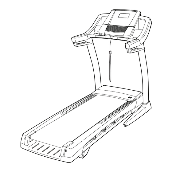
BEFORE YOU BEGIN Thank you for selecting the revolutionary reading this manual, please see the front cover of this NORDICTRACK C 900 treadmill. The C 900 treadmill manual. To help us assist you, please note the product ® offers an impressive selection of features designed model number and serial number before contacting us. -
Page 7: Part Identification Chart
PART IDENTIFICATION CHART Use the drawings below to identify small parts used for assembly. The number in parentheses below each draw- ing is the key number of the part, from the PART LIST near the end of this manual. The number following the key number is the quantity used for assembly. -
Page 8: Assembly
ASSEMBLY •• To watch an assembly •• Left parts are marked ““L”” or ““Left”” and right parts video, go to are marked ““R”” or ““Right.”” http://productvideo.co/ assembly/sears/ •• To identify small parts, see page 7. nordictrack or use your mobile phone or smart- ••... - Page 9 2. Pull the Upright Wire (81) and the ground wire (A) through the indicated hole in the Base (94). Attach the ground wire (A) to the Base (94) with a Square #8 x 1/2" Silver Screw (10). Hole Hole Press the Grommet (77) into the square hole in the Base (94).
- Page 10 4. Hold the Left Upright (89) against the Base (94). Be careful not to pinch any wires. Insert two 3/8" x 2 1/4" Screws (7) and two 3/8" x 1 1/4" Screws (8) with two 3/8" Star Washers (13) into the Left Upright.
- Page 11 6. Identify the left handrail assembly (B). Hold the left handrail assembly (B) near the Left Upright (89). Insert the wire tie on the Upright Wire (81) into the bottom and out of the top of the left handrail as shown. Then, pull the Upright Wire through the left handrail.
- Page 12 8. Set the Console Base (64) face down on a soft surface to avoid scratching the Console Base. Remove the two screws (E) from the Pulse Crossbar (93). Remove the Pulse Crossbar and discard the screws. Remove and save the four 5/16" x 3/4" Screws (4) from the Console Frame (104).
- Page 13 10. IMPORTANT: To avoid damaging the Pulse Crossbar (93), do not use power tools and do not overtighten the #10 x 3/4" Screws (9). Orient the Pulse Crossbar (93) as shown. Attach the Pulse Crossbar to the Handrails (86) with four #10 x 3/4"...
- Page 14 12. Set the console assembly on the brackets on the Handrails (86). Make sure that no wires are Console pinched. Insert the excess Upright Wire (81) Assembly behind the Console Frame (104). Attach the console assembly to the brackets on the Handrails (86) with the four 5/16" x 3/4" Screws (4) removed in step 8 and four 5/16"...
- Page 15 15. Tighten a #8 x 3/4" Screw (2) into the Left Outside Upright Cover (87) and into the bottom of the left handrail assembly (C). Make sure not to overtighten the Screw. Press the Left Inside Upright Cover (88) against the Left Outside Upright Cover (87) until they ““snap””...
- Page 16 17. Raise the Frame (56) to the position shown. Have a second person hold the Frame until step 18 is completed. Orient the Storage Latch (53) so that the large barrel and the latch knob are oriented as shown. Attach the lower end of the Storage Latch (53) to the Base (94) with a 3/8"...
-
Page 17: Operation And Adjustment
OPERATION AND ADJUSTMENT HOW TO CONNECT THE POWER CORD nominal 120-volt circuit capable of carrying 15 or more amps. To avoid overloading the circuit, do Use a Surge Suppressor not plug other electrical devices, except for low- power devices such as cell phone chargers, into Your treadmill, like other electronic equipment, can be the surge suppressor or into an outlet on the same damaged by sudden voltage changes in your home’’s... - Page 18 CONSOLE DIAGRAM FEATURES OF THE CONSOLE You can even listen to your favorite workout music or audio books with the console’’s stereo sound system The treadmill console offers an impressive array of while you exercise. features designed to make your workouts more effec- tive and enjoyable.
- Page 19 HOW TO TURN ON THE POWER HOW TO USE THE MANUAL MODE IMPORTANT: If the treadmill has been exposed to 1. Insert the key into the console. cold temperatures, allow it to warm to room tem- perature before you turn on the power. If you do See HOW TO TURN ON THE POWER at the left.
- Page 20 4. Change the incline of the treadmill as desired. The My Trail tab will show a track that represents 1/4 mile (400 m). As you exercise, the white rect- To change the incline of the treadmill, press the angle will show your progress. The My Trail tab will Incline increase or decrease button or one of the also show the number of laps you complete.
- Page 21 6. Measure your heart rate if desired. Press the small fan but- ton repeatedly to select Before using a fan speed or to turn off the handgrip the fan. Press the large heart rate moni- Auto fan button to select tor, remove the the auto mode or to turn sheets of plastic...
- Page 22 HOW TO USE AN ONBOARD WORKOUT The workout will continue in this way until the last segment of the pro le ashes in the display and the 1. Insert the key into the console. last segment ends. The walking belt will then slow to a stop.
- Page 23 HOW TO USE A SET-A-GOAL WORKOUT HOW TO USE AN IFIT WORKOUT 1. Insert the key into the console. Note: To use an iFit workout, you must have an optional iFit module. To purchase an iFit module at See HOW TO TURN ON THE POWER on page 19. any time, go to www.iFit.com or call the telephone number on the front cover of this manual.
- Page 24 For more information about the iFit workouts, 7. Measure your heart rate if desired. please see www.iFit.com. See step 6 on page 21. When you select an iFit workout, the display will show the name, duration, maximum speed setting, 8. Turn on the fan if desired. and distance of the workout.
- Page 25 THE INFORMATION MODE into the reset position, and insert the key into the console. However, when you remove the key, the The console features an information mode that keeps displays will remain lit, although the buttons will not track of treadmill information and allows you to person- function.
-
Page 26: How To Fold And Move The Treadmill
HOW TO FOLD AND MOVE THE TREADMILL HOW TO FOLD THE TREADMILL HOW TO MOVE THE TREADMILL To avoid damaging the treadmill, adjust the incline Before moving the treadmill, fold it as described at the to the lowest position before you fold the treadmill. left. -
Page 27: Troubleshooting
TROUBLESHOOTING Most treadmill problems can be solved by following c. Remove the key from the console, and then the simple steps below. Find the symptom that reinsert it. applies, and follow the steps listed. If further assis- tance is needed, see the front cover of this manual. d. - Page 28 Locate the Reed Switch (52) and the Magnet (50) b. If the walking belt is overtightened, treadmill per- on the left side of the Pulley (49). Turn the Pulley formance may decrease and the walking belt may until the Magnet is aligned with the Reed Switch. become damaged.
- Page 29 SYMPTOM: The walking belt is off-center or slips b. If the walking belt slips when walked on, rst when walked on remove the key and UNPLUG THE POWER CORD. Using the hex key, turn both idler roller a. If the walking belt is off-center, rst remove the screws clockwise, 1/4 of a turn.
-
Page 30: Exercise Guidelines
EXERCISE GUIDELINES Burning Fat——To burn fat effectively, you must exer- WARNING: cise at a low intensity level for a sustained period of Before beginning this time. During the first few minutes of exercise, your or any exercise program, consult your physi- body uses carbohydrate calories for energy. -
Page 31: Part List
PART LIST Model No. 29450.0 R0213A Key No. Qty. Description Key No. Qty. Description #8 x 1/2" Screw Motor Belt #8 x 3/4" Screw Frame 3/8" x 2" Bolt Left Rear Foot 5/16" x 3/4" Screw Frame Endcap Cover #10 Star Washer Rubber Cushion 3/8"... -
Page 32: Exploded Drawing
EXPLODED DRAWING A Model No. 29450.0 R0213A... - Page 33 EXPLODED DRAWING B Model No. 29450.0 R0213A...
- Page 34 EXPLODED DRAWING C Model No. 29450.0 R0213A...
- Page 35 EXPLODED DRAWING D Model No. 29450.0 R0213A...
-
Page 36: Ordering Replacement Parts
ORDERING REPLACEMENT PARTS To order replacement parts, please see the front cover of this manual. To help us assist you, be prepared to pro- vide the following information when contacting us: •• the model number and serial number of the product (see the front cover of this manual) ••...
Need help?
Do you have a question about the 29450.0 and is the answer not in the manual?
Questions and answers