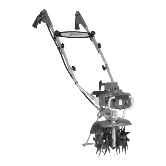
Summary of Contents for Mantis 7234 DELUXE
- Page 1 IMPORT NT! SSEMBLY INSTRUCTIONS ST RT ON P GE 5! PLE SE REVIEW THE W RNING & S FETY INFORM TION ON P GES 3-4 ND THE SSEMBLY INSTRUCTIONS BEFORE UNP CKING THE BOX.
- Page 3 W RNING • D NGER W RNING • D NGER W RNING • D NGER EMISSION CONTROL An Emission Control Label W RNING • D NGER W RNING • D NGER...
- Page 4 W RNING • D NGER...
- Page 5 W RNING • D NGER...
- Page 6 B – Right Qty. Part No. Description Transmission and Engine assembly C – Left D – Loop handle grip B, C – Loop Handle 430023 Loop handle right half 430022 Loop handle left half A – Transmission and 430025 Loop handle grip Engine Assembly 1/4-20 H –...
- Page 7 Z – Kickstand Brace Kit Y – Kickstand V, W – Tines X – Tine Retaining pins Qty. Part No. Description Qty. Part No. Description 410158 Stand 438RA Tine assembly, right 430037 Kickstand Brace Kit 438LA Tine assembly, left 418-1 Tine retaining pins F–...
- Page 8 IMPORT NT 1/4-20 H – 1/4-20 x J – Two-way 1-1/8 Hex head lock nut cap screws I – Carry Handle w/grip Z – Kickstand Brace Kit Y – Kickstand...
- Page 9 V, W – Tines X – Tine Retaining pins 1/4-20 x 1-1/8 Hex J – head cap screws 1/4-20 H – O – Handle Brace Two-way lock nut M-Right K-Right N-Left L-Left M, N –Middle K, L – Handle Assembly handles...
- Page 10 S – Curved Q – Knobs, Two- Head Bolts Prong female Q – Knobs, Two- R – Carriage Prong female Bolts...
- Page 12 W RNING • D NGER W RNING • D NGER ollow these steps whenever you are starting the engine “cold”, or when the engine has run dry and you have just added fuel.
- Page 13 W RNING W RNING • D NGER W RNING...
- Page 14 W RNING...
- Page 15 W RNING • D NGER...
- Page 16 W RNING • D NGER...
- Page 18 W RNING•D NGER W RNING•D NGER...
- Page 19 W RNING•D NGER W RNING...
- Page 21 ITEM QTY PART # DESCRIPTION ITEM QTY PART # DESCRIPTION...


Need help?
Do you have a question about the 7234 DELUXE and is the answer not in the manual?
Questions and answers