Table of Contents
Advertisement
Advertisement
Table of Contents

Subscribe to Our Youtube Channel
Related Manuals for Samson C COM16


Summary of Contents for Samson C COM16
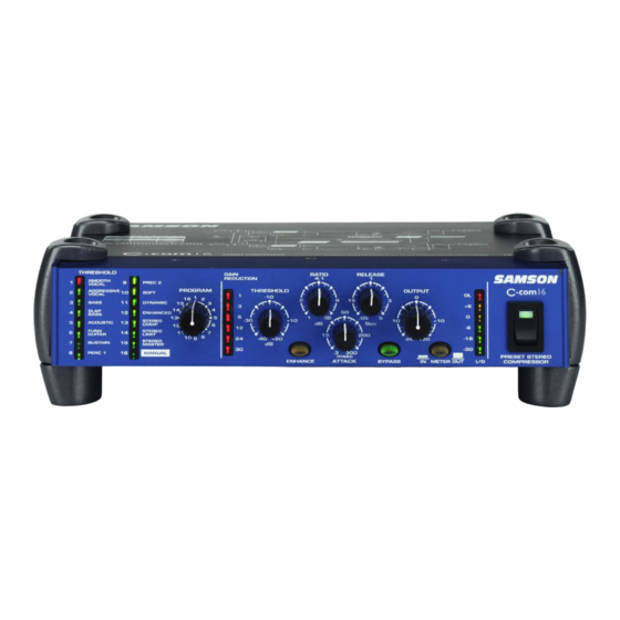
- Page 1 PRE-SET STEREO COMPRESSOR...
-
Page 2: Safety Instructions
Safety Instructions Caution: To reduce the hazard of electrical shock, do not remove cover or back. No user serviceable parts inside. Please refer all servicing to qualified personnel. WARNING: To reduce the risk of fire or electric shock, do not expose this unit to rain or moisture. The lightning flash with an arrowhead symbol within an equilateral triangle, is intended to alert the user to the presence of uninsulated "dangerous voltage"... -
Page 3: Table Of Contents
C com 16 Wiring Tilting and Stacking the C com 16 C Class Dual Rack Adaptor (optional) Specifications Block Diagram Copyright 2003, Samson Technologies Corp. Printed Febraury, 2003 Samson Technologies Corp. 575 Underhill Blvd. P.O. Box 9031 Syosset, NY 11791-9031... -
Page 4: Introduction
Introduction Congratulations on purchasing the C com 16, pre-set stereo compressor by Samson Audio! The C com 16 is a compact, high-quality device that provides extensive dynamics processing and control that has previously only been found in expensive outboard devices. The C com 16 is the easiest to operate compressor ever made. -
Page 5: C Com 16 Features
Advanced electronics incorporating high quality VCA’s and low noise op-amps providing a transparent signal path. • Oversized, rubber bumpers with tilting feet allow several Samson C class units to be stacked and tilted in an ergonomically correct operating position. •... -
Page 6: Front Panel Layout
C com 16 Front Panel Layout C com 16 Front Panel Layout PROGRAM LED’S 1- 8 – When illuminated, indicates 8 OUTPUT - Used to set the final level after the com- the associated Program (1-SMOOTH VOCAL, 2- pression circuit is applied. AGGRESSIVE VOCAL, 3-BASS, 4-SLAP BASS, 5- ACOUSTIC, 6-FUNK GUITAR, 7-SUSTAIN, 8-PERC 1) is 9 INPUT/OUTPUT METER - Six segment LED meter... -
Page 7: Rear Panel Layout
C com 16 Rear Panel Layout C com 16 Rear Panel Layout A AC INLET - The included AC power supply is con- – 1/4-inch TRS (TIP/RING/SLEEVE) KEY INSERT nected here. phone input/output connector used to exter- nally process the compressors trigger signal. - 1/4-inch, TRS (TIP/RING/SLEEVE) LEFT OUTPUT phone connector for the LEFT line-level, balanced... -
Page 8: Quick Start
QUICK START Quick Start - Set-up Setting up your C com 16 is a simple procedure, which takes only a few minutes. There are many ways to inter- face the C com 16 with various recording or live sound set-ups, so take some time to decide which audio devices you want to connect. -
Page 9: Default Positions
QUICK START Quick Start - Set-up - continued • Plug the C com16’s power pack into a wall outlet and switch the unit on by pressing the power switch. • Next, turn on your mixer, but don’t turn on your power amp or powered monitors just yet. Quick Start - Default Position •... -
Page 10: Operating The C Com 16
Operating The C com 16 Connecting the C com 16 The C com 16 can be easily connected to most any audio device thanks to the use of standard 1/4-inch phone connectors, and to the +4/-10 switch input level switch. You can use your C com 16 in a mixers insert point, or in-line between your instrument or other line level audio device. -
Page 11: Setting Input And Output Levels
Operating The C com 16 Setting Input and Output Levels - continued SENSITIVITY It is important to undertstand how the C com 16’s SENSITIVITY control works since it has a dual purpose. First, to control the input level, and second, to con- trol the relative threshold level for the comressor cicuit. -
Page 12: Using The Program Pre-Sets
Operating The C com 16 Using the Program Pre-sets - continued PROGRAM Control The PROGRAM control is used to select one of the 15 pre- sets, or the MANUAL mode. When you dial through the pre-sets using the PROGRAM control, you will see the cor- responding PRESET LED turn from RED to GREEN. -
Page 13: Compressing A Signal In Manual Mode
Operating The C Com 16 Operation the C com 16 In MANUAL Mode - continued RELEASE The RELEASE control is used to set how long the compressor takes to return the input signal back to its original level once the signal falls below the threshold level. -
Page 14: Using The Enhancer
Operating The C Com 16 USING THE ENHANCER ENHANCER The C Com 16’s ENHANCER switch can be engaged to activate the EFR (Enhanced Frequency Recovery) circuit. By engaging the ENHANCER, the C Com 16 EFR restores the high frequency content that can be lost when high gain reduction is applied. -
Page 15: Dynamics Processing 101
Dynamics Processing 101 To begin to understand dynamics processing, we must first understand what dynamics are. Dynamics, or the dynamic range of a signal or audio device, is the amount of level between the softest and loudest possible output. Dynamics processing is applied to a signal to manage the changes in level. Various types of processing units are available to control dynamics including Noise Gates, Expanders, Compressors, Limiters and De-Essers. - Page 16 Noise gates often have other adjustable controls like attack, hold, range and release. Many noise gates like those in the SAMSON S com, S com plus, S com 4 and S gate 4 use sophisticated circuits to control some of these parameters automatically.
-
Page 17: Applications
Applications Leveling a Vocal Track When recording a vocal track, the vocalist may change the distance between them and the microphone, or they may naturally have a lot of dynamic range in their performance. In either case, the sound engineer must decide how much compression should be used to balance the natural performance and printing a good level to tape or disk. -
Page 18: System Set-Ups
C Com 16 System Set-Ups LIVE SOUND SYSTEM WITH STEREO COMPRESSION In this example, the C Com 16 is inserted after the mixer and before the graphic equalizer, thereby compressing the full range signal from the mixer. COMPRESSION SUBGROUPS ON INSERT POINTS In this example, two C Com 16’s are connected to the the mixer’s insert points on the subgroup outputs. - Page 19 C Com 16 Connections CONNECTING THE C Com 16 There are several ways to interface the C Com 16 to support a variety of applications. The C Com 16 features servo-balanced inputs and outputs, so connecting balanced and unbalanced signals is possible without any sig- nal loss.
-
Page 20: Tilting And Stacking The C Com 16
Stacking the C com 16 You can stack one C com 16, or any other Samson C Class units, on top of each other by simply lining up the bumpers. Important Note: When stacking the C COM 16, be sure that only the bottom unit has the tilting feet installed. - Page 21 To remove the C•Class unit from the C•Rack, reverse the instructions above. If you experience any difficulties, or require further assistance, contact Samson Customer Service at 1-800-3SAMSON (1-800- 372-6766) M–F 9AM to 5PM (eastern standard time). For more product information please visit our website at www.samson- tech.com.
-
Page 22: Specifications
Specifications System Specifications Frequency Response 20Hz to 20kHz + - 0.5 dB Dynamic range 95 dBu, un-weighted, 22 Hz to 22 kHz 0.008 % typ. @ +4 dBu, 1 kHz Crosstalk 90dB 22 Hz to 22 kHz Detector Compressor Section Sensitivity -10 dB to +20 dB ∞... -
Page 23: Block Diagram
Block Diagram... - Page 24 Samson Technologies Corp. 575 Underhill Blvd. P.O. Box 9031 Syosset, NY 11791-9031 Phone: 1-800-3-SAMSON (1-800-372-6766) Fax: 516-364-3888 www.samsontech.com...
Need help?
Do you have a question about the C COM16 and is the answer not in the manual?
Questions and answers