Lochinvar Knight 151 Installation & Operation Manual
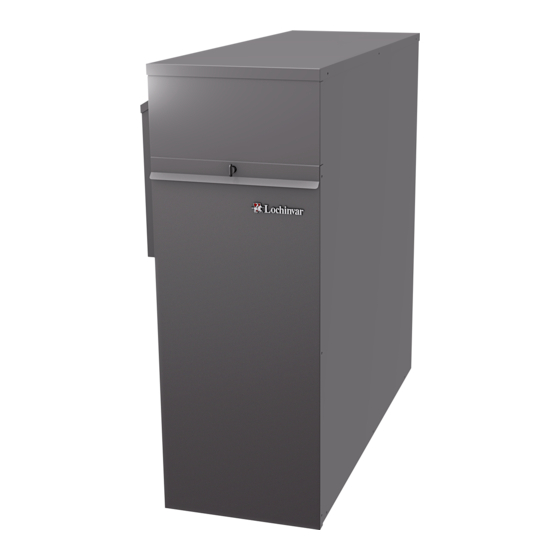
Outdoor knight boiler
Hide thumbs
Also See for Knight 151:
- Installation & operation manual (76 pages) ,
- Service manual (40 pages) ,
- Instructions manual (40 pages)
Table of Contents
Advertisement
Quick Links
OKB-I-O Rev C
Outdoor Knight Boiler
Installation & Operation
Manual
Models: 151 - 286
This manual must only be used by
WARNING
a qualified heating installer / service
technician. Read all instructions,
including this manual and the
Outdoor Knight Boiler Service
Manual, before installing. Perform
steps in the order given.
Failure
to comply could result in severe
personal injury, death, or substantial
property damage.
Save this manual for future reference.
Advertisement
Table of Contents

Related Manuals for Lochinvar Knight 151


Summary of Contents for Lochinvar Knight 151
- Page 1 OKB-I-O Rev C Outdoor Knight Boiler Installation & Operation Manual Models: 151 - 286 This manual must only be used by WARNING a qualified heating installer / service technician. Read all instructions, including this manual and the Outdoor Knight Boiler Service Manual, before installing.
-
Page 2: Table Of Contents
Contents HAZARD DEFINITIONS ............ 2 5. FIELD WIRING PLEASE READ BEFORE PROCEEDING ......3 Line Voltage Connections ..........28 THE OUTDOOR KNIGHT BOILER -- HOW IT WORKS 4-6 Low Voltage Connections ..........28 RATINGS ................7 Wiring of the Cascade ............30 1. -
Page 3: Please Read Before Proceeding
Outdoor Knight Boiler Installation & Operation Manual Please read before proceeding When servicing boiler – Installer – Read all instructions, including WARNING this manual and the Outdoor Knight • To avoid electric shock, disconnect electrical supply Boiler Service Manual, before installing. before performing maintenance. -
Page 4: The Outdoor Knight Boiler - How It Works
Outdoor Knight Boiler Installation & Operation Manual The Outdoor Knight Boiler - How it works... Stainless steel heat exchanger 17. Manual air vent Allows system water to flow through specially designed Designed to remove trapped air from the heat exchanger coils for maximum heat transfer, while providing coils. - Page 5 Outdoor Knight Boiler Installation & Operation Manual The Outdoor Knight Boiler - How it works... (continued) Models 151 - 211 IMG00366 IMG00365 IMG00365 Front View - Models 151 - 211 Rear View - Models 151 - 211 IMG00368 IMG00367 Right Side (inside unit) - Models 151 - 211 Left Side (inside unit) - Models 151 - 211...
-
Page 6: The Outdoor Knight Boiler -- How It Works
Outdoor Knight Boiler Installation & Operation Manual The Outdoor Knight Boiler - How it works... Model 286 IMG00380 IMG00379 Rear View - Model 286 Front View - Model 286 IMG00381 IMG00382 Left Side (inside unit) - Model 286 Right Side (inside unit) - Model 286... -
Page 7: Ratings
Maximum allowed working pressure is located on the rating plate. NOTICE Notes: 1. As an Energy Star Partner, Lochinvar has determined that outdoor boilers meet the Energy Star guidelines for energy efficiency. 2. The ratings are based on standard test procedures prescribed by the United States Department of Energy. -
Page 8: Determine Boiler Location
Outdoor Knight Boiler Installation & Operation Manual Determine boiler location Installation must comply with: Do not locate unit so that high winds can CAUTION deflect off of adjacent walls, buildings • Local, state, provincial, and national codes, laws, shrubbery causing recirculation. -
Page 9: Provide Clearances
Outdoor Knight Boiler Installation & Operation Manual Determine boiler location (continued) Flooring and foundation Provide clearances: Clearances from combustible materials Flooring 1. Hot water pipes—at least 1/4" (6 mm) from combustible The Outdoor Knight is approved for installation on combustible materials. -
Page 10: Prepare Boiler
Outdoor Knight Boiler Installation & Operation Manual Prepare boiler Remove boiler from wood pallet Figure 2-2 Install Flue Pipe Assembly 1. After removing the outer shipping carton from the boiler, remove the installation kit. WALL STRAP SCREWS 2. Remove the front access covers to access the lag bolts in BIRD SCREEN WALL STRAP front of the unit (FIG. -
Page 11: Leveling The Boiler
Outdoor Knight Boiler Installation & Operation Manual Prepare boiler (continued) Leveling the boiler 5. After installation is complete, attach the propane conversion label (in the conversion kit bag) next to the Set the boiler in place and check level. boiler rating plate. Attach the LP caution label (in the a) Adjust legs if necessary to level boiler, see FIG. -
Page 12: Hydronic Piping
Outdoor Knight Boiler Installation & Operation Manual Hydronic piping System water piping methods General piping information The outdoor boiler is designed to function in a closed loop Basic steps are listed in this section along with illustrations on pressurized system not less than 12 psi. A temperature and the following pages (FIG.’s 3-4 thru 3-10), which will guide you pressure gauge is included to monitor system pressure and through the installation of the outdoor boiler (reference FIG.’s... -
Page 13: Relief Valve / T & P Installation
Outdoor Knight Boiler Installation & Operation Manual Hydronic piping (continued) Near boiler piping components The relief valve, tee and any necessary fittings WARNING are shipped in the install kit with the boiler 1. Boiler system piping: and are to be field installed (FIG. 3-1). Boiler system piping MUST be sized per the pipe requirements listed in Table 3A. -
Page 14: Near Boiler Piping Connections
Outdoor Knight Boiler Installation & Operation Manual Hydronic piping 12. System temperature sensor: Lochinvar offers the Squire which is a series of indirect Lochinvar supplies a system temperature sensor. water heaters. The Squire features a stainless steel vessel The sensor is to be installed in the heating loop with a single wall stainless steel heat exchanger. - Page 15 Outdoor Knight Boiler Installation & Operation Manual Hydronic piping (continued) Figure 3-3 Pressure Drop vs. Flow Pressure Drop vs. Flow (Includes Secondary Piping) 10 11 12 13 14 15 16 17 18 19 20 21 22 23 24 25 Flow Rate (GPM) Table 3A Circulator Recommendations for Temperature Rise Applications_20°, 25°, and 35°...
-
Page 16: Variable Speed Pump Option
When using more than one temperature demand it is necessary to protect the lower temperature loop from overheating. To help aid with this protection, Lochinvar offers the Multi- Temperature Loop Control Board Kit (RLY30086). - Page 17 Outdoor Knight Boiler Installation & Operation Manual Hydronic piping (continued) Figure 3-4 Single Boiler - Single Temperature Zoned with Circulators ZONE #1 PRESSURE PRESSURE ZONE #2 ZONE #3 ZONE #4 GAUGE REDUCING VALVE BACKFLOW FLOW CHECK PREVENTER VALVE (TYPICAL) MAKE UP WATER SYSTEM SUPPLY SENSOR ZONE CIRCULATORS...
- Page 18 Outdoor Knight Boiler Installation & Operation Manual Hydronic piping Figure 3-5 Multiple Boilers - Single Temperature Zoned with Circulators Number of Units Model Required Pipe Sizes 2" 2" 2-1/2" 2-1/2" 3" 3" 3-1/2" 2" 2-1/2" 3" 3" 3-1/2" 4" 4" 2-1/2"...
- Page 19 Outdoor Knight Boiler Installation & Operation Manual Hydronic piping (continued) Figure 3-6 Single Boiler - Multiple Temperatures PRESSURE TEMPERATURE TEMPERATURE REDUCING VALVE TEMPERATURE LOOP #1 LOOP #2 LOOP #3 WIRES TO LOOP SENSORS BACKFLOW PREVENTER PRESSURE GAUGE MAKE SYSTEM WATER MIXING VALVES SUPPLY (TYPICAL)
- Page 20 Outdoor Knight Boiler Installation & Operation Manual Hydronic piping Figure 3-7 Multiple Boilers - Multiple Temperatures Number of Units Model Required Pipe Sizes 2" 2" 2-1/2" 2-1/2" 3" 3" 3-1/2" 2" 2-1/2" 3" 3" 3-1/2" 4" 4" 2-1/2" 2-1/2" 3" 3-1/2"...
- Page 21 Outdoor Knight Boiler Installation & Operation Manual Hydronic piping (continued) Figure 3-8 Single Boiler - Multiple Temperatures with DHW Piped as a Zone PRESSURE TEMPERATURE TEMPERATURE WIRES TO TEMPERATURE REDUCING VALVE LOOP #1 LOOP #2 LOOP LOOP #3 BACKFLOW SENSORS PREVENTER PRESSURE GAUGE...
- Page 22 Outdoor Knight Boiler Installation & Operation Manual Hydronic piping Figure 3-9 Multiple Boilers - Single Temperature Zoned with Valves Number of Units Model Required Pipe Sizes 2" 2" 2-1/2" 2-1/2" 3" 3" 3-1/2" 2" 2-1/2" 3" 3" 3-1/2" 4" 4" ZONE #1 2-1/2"...
- Page 23 Outdoor Knight Boiler Installation & Operation Manual Hydronic piping (continued) Figure 3-10 Multiple Boilers - Non-Zoned Primary/Secondary Piping Number of Units Model Required Pipe Sizes 2" 2" 2-1/2" 2-1/2" 3" 3" 3-1/2" 2" 2-1/2" 3" 3" 3-1/2" 4" 4" 2-1/2" 2-1/2" 3"...
-
Page 24: Gas Connections
Outdoor Knight Boiler Installation & Operation Manual Gas connections Connecting gas supply piping 4. Purge all air from the gas supply piping. 1. Remove the top access cover and refer to FIG. 4-1 to pipe 5. Before placing the boiler in operation, check the boiler gas to the boiler. -
Page 25: Natural Gas
Outdoor Knight Boiler Installation & Operation Manual Gas connections (continued) Natural gas: Use two wrenches when tightening gas WARNING piping at boiler (FIG. 4-2), using one Pipe sizing for natural gas wrench to prevent the boiler gas line connection from turning. Failure to 1. -
Page 26: Check Inlet Gas Supply
Outdoor Knight Boiler Installation & Operation Manual Gas connections Table 4A Natural Gas Pipe Size Chart Single Unit Nominal Natural Gas Pipe Capacity Chart Iron Pipe Length of Pipe in Straight Feet for 1/2 PSI Size (Inches) 1-1/4 1400 1-1/2 2150 1500 1210... -
Page 27: Gas Pressure
Outdoor Knight Boiler Installation & Operation Manual Gas connections (continued) Gas Pressure When re-tightening the set screw, be sure WARNING to tighten securely to prevent gas leaks. The gas pressure must remain between 4 inches w.c. (natural), Do not check for gas leaks with an open 8 inches w.c. -
Page 28: Field Wiring
Outdoor Knight Boiler Installation & Operation Manual Field wiring ELECTRICAL SHOCK HAZARD – For Label all wires prior to disconnection WARNING CAUTION your safety, turn off electrical power supply when servicing controls. Wiring errors before making any electrical connections can cause improper and dangerous to avoid possible electric shock hazard. -
Page 29: Outdoor Temperature Sensor
2. The tank sensor included with the Lochinvar Squire terminals 1 and 3 on connector X5 on the optional ModBus Indirect DHW tank (TST20015) is the only sensor interface module. -
Page 30: Wiring Of The Cascade
Outdoor Knight Boiler Installation & Operation Manual Field wiring Flow switch Runtime contacts 1. A flow switch is used to guarantee flow through the The SMART SYSTEM control closes a set of dry contacts boiler before allowing it to fire. The flow switch must be whenever the burner is running. - Page 31 Outdoor Knight Boiler Installation & Operation Manual Field wiring (continued) Figure 5-3 Low Voltage Field Wiring Connections...
-
Page 32: Condensate Disposal Condensate Drain
Outdoor Knight Boiler Installation & Operation Manual Condensate disposal Condensate drain Use materials approved by the authority NOTICE having jurisdiction. In the absence of 1. This boiler is a high efficiency appliance that produces other authority, PVC and CPVC pipe condensate. -
Page 33: Startup
Outdoor Knight Boiler Installation & Operation Manual Start-up Check/control water chemistry 3. Fill to correct system pressure. Correct pressure will vary with each application. Do not use petroleum-based cleaning or CAUTION The minimum cold water fill pressure for a sealing compounds in the boiler system. residential system is 12 psi. -
Page 34: Check For Gas Leaks
Outdoor Knight Boiler Installation & Operation Manual Start-up Check for gas leaks Propane boilers only – Your propane WARNING supplier mixes an odorant with the propane Before starting the boiler, and during to make its presence detectable. In some WARNING initial operation, smell near the floor and instances, the odorant can fade, and the around the boiler for gas odorant or any... -
Page 35: Start The Boiler
Outdoor Knight Boiler Installation & Operation Manual Start-up (continued) Final checks before starting the boiler Check gas piping Read the Outdoor Knight Boiler Service Manual to 1. Check around the boiler for gas odor following the familiarize yourself with SMART SYSTEM control procedure on page 24 of this manual (connecting gas supply module operation. - Page 36 Outdoor Knight Boiler Installation & Operation Manual Start-up Figure 7-2 Operating Instructions...
-
Page 37: Set Space Heating Operation
Outdoor Knight Boiler Installation & Operation Manual Start-up (continued) Check flame and combustion Set space heating operation (continued) Please note that the brackets ([]) denote Determine controlling sensor NOTICE screen status. For space heating systems, the temperature control can be based on one of three sensors;... -
Page 38: Startup
Outdoor Knight Boiler Installation & Operation Manual Start-up Set domestic hot water (DHW) operation Verify DHW mode Turn the NAVIGATION dial to adjust the month. Press the There are two (2) modes of operation for DHW. In Normal NAVIGATION dial. Mode, when a DHW demand begins, the control will start Turn the NAVIGATION dial to adjust the date. -
Page 39: Operating Information General
Freeze Protection separate loops, based on the settings for the three (3) heat/loop Mode ends. demands (reference Lochinvar kit RLY30086). The system pump will run whenever there is a space heating 0 - 10V input (set point or power) call for heat, or the boiler goes into Freeze Protection Mode. -
Page 40: Temperature Control
Outdoor Knight Boiler Installation & Operation Manual Operating information Temperature control Protection features Modulation Outlet temperature, flue temperature, The outdoor boiler is capable of modulating its firing rate temperature rise limiting from a minimum of 20% to a maximum of 100%. The The outlet temperature is monitored by the boiler outlet firing rate is dictated by the call for heat (i.e., space heating temperature sensor. - Page 41 Outdoor Knight Boiler Installation & Operation Manual Operating information (continued) When the outlet temperature exceeds 200°F, the automatic Monitor external limits high limit action occurs. The boiler shuts down until the outlet Connections are provided on the connection board for water temperature cools below 190°F, and a 60 second timer external limits such as a flow switch, low water cutoff and has expired.
-
Page 42: Cascade
Outdoor Knight Boiler Installation & Operation Manual Operating information Outdoor reset operation Sequence of the cascade Target temperature with outdoor reset To equalize the run time of all boilers on the Cascade, the firing sequence will automatically be changed at set intervals. This feature improves the system's efficiency by decreasing set point as the outdoor temperature warms up. -
Page 43: Sequence Of Operation
Outdoor Knight Boiler Installation & Operation Manual Operating information (continued) Sequence of operation OPERATION DISPLAY 1. Upon a call for heat, the gas pressure switch(es) must be closed. 2. Once the gas pressure switch(es) are closed, the control turns on the appropriate pumps (system and boiler pumps for space heating, DHW pump for DHW). - Page 44 Outdoor Knight Boiler Installation & Operation Manual Operating information Sequence of operation (continued) OPERATION DISPLAY 8. If the space heating call for heat is active, and the tank thermostat or sensor starts a DHW call for heat, the boiler will switch to the DHW mode.
-
Page 45: Outdoor Knight Boiler Control Module
Outdoor Knight Boiler Installation & Operation Manual Operating information (continued) Outdoor Knight boiler control module Use the control panel (FIG. 8-1) to set temperatures, operating conditions, and monitor boiler operation. Figure 8-1 Control Panel NAVIGATION DIAL (PRESS OR TURN) The information on the bottom of the display shows the functions of the two SELECT keys (on either corner), and the NAVIGATION dial (in the center): MENU = Left SELECT Key SETPOINTS = NAVIGATION Dial - Pressing Down... -
Page 46: Status Display Screens
Outdoor Knight Boiler Installation & Operation Manual Operating information Figure 8-2 Status Display Screen (CALL FOR (BOILER HEAT) STATUS) (OPERATIONAL INFORMATION) (RIGHT SELECT KEY) (LEFT SELECT KEY) (NAVIGATION DIAL) Status Display Screens Section Display Description The unit has not received a call for heat from a remote thermostat nor STANDBY has it received a call for heat from a DHW thermostat. - Page 47 Outdoor Knight Boiler Installation & Operation Manual Operating information (continued) Status Display Screens (cont’d) Section Display Description SYSTEM: The temperature read by the system supply sensor (if connected). TANK: The temperature read by the tank sensor (if connected). OUTDOOR: The temperature read by the outdoor sensor. INLET TEMP: The temperature read at the inlet to the heat exchanger.
-
Page 48: Status Display Screens
Outdoor Knight Boiler Installation & Operation Manual Operating information Status Display Screens (cont’d) Section Display Description Press and hold the LEFT SELECT key for 5 seconds to enter the Menu MENU Screen. EXIT Press the LEFT SELECT key to exit the current screen or setting. Press the LEFT SELECT key to confirm that the boiler needs to shutdown. -
Page 49: Maintenance
Outdoor Knight Boiler Installation & Operation Manual Maintenance Maintenance and annual startup Table 9A Service and Maintenance Schedules Owner maintenance Service technician (see the Outdoor Knight User’s Information Manual (see the following pages for instructions) for instructions) • Check boiler area General: •... -
Page 50: Address Reported Problems
Outdoor Knight Boiler Installation & Operation Manual Maintenance Follow the service and maintenance procedures given throughout this manual and in component literature WARNING shipped with the boiler. Failure to perform the service and maintenance could result in damage to the boiler or system. -
Page 51: Check Expansion Tank
Outdoor Knight Boiler Installation & Operation Manual Maintenance (continued) Flue vent system and air piping Safety relief valves should be re-inspected WARNING AT LEAST ONCE EVERY THREE YEARS, Visually inspect the entire flue gas venting system and air by a licensed plumbing contractor or piping for blockage, deterioration or leakage. -
Page 52: Check Burner Flame
Outdoor Knight Boiler Installation & Operation Manual Maintenance Inspect ignition and flame sense Check burner flame electrodes 1. Inspect flame through observation window. 1. Remove the ignition and flame sense electrodes from the 2. If the flame is unsatisfactory at either high fire or low fire, boiler heat exchanger access cover. -
Page 53: Review With Owner
Outdoor Knight Boiler Installation & Operation Manual Maintenance (continued) Review with owner 11. Close isolation valves on piping to isolate boiler from system. Attach a hose to the boiler drain and flush boiler 1. Review the Outdoor Knight Boiler User’s Information thoroughly with clean water by using purging valves to Manual with the owner. -
Page 54: Diagrams
Outdoor Knight Boiler Installation & Operation Manual Diagrams Figure 10-1 Ladder Diagram JUNCTION BOX 120VAC NEUTRAL GROUND TERMINAL STRIP TERMINAL STRIP 120V SUPPLY "L" 120V SUPPLY "N" INTEGRATED CONTROL BLOWER ON / OFF KB ONLY SWITCH SYSTEM SYSTEM X1-1 X1-6 PUMP "L"... -
Page 55: Wiring Diagram
Outdoor Knight Boiler Installation & Operation Manual Diagrams (continued) Figure 10-2 Wiring Diagram LOW VOLTAGE BOX DEPICTS 120 VAC OPTIONAL ITEMS HIGH VOLTAGE BOX DEPICTS DUAL SENSOR SINGLE HOUSING INTEGRATED CONNECTION BOARD BOX DEPICTS CONTROL JUNCTION OPTIONAL ITEMS ALARM X1-3 CONTACTS PUMP RUN-TIME... -
Page 56: Revision Notes
Revision Notes: Revision A (ECO C11234) initial release. Revision B (ECO #C11235) reflects updates made to the freezing conditions warnings. Revision C (ECO #C11736) reflects changes made to the ratings page (page 7). OKB-I-O Rev C 11/12...
Need help?
Do you have a question about the Knight 151 and is the answer not in the manual?
Questions and answers