Table of Contents
Advertisement
Quick Links
NOTE:
Please read all instructions
carefully before using this
product
Safety Notice
Hardware Identifier
Assembly Instruction
Parts List
Warranty
Ordering Parts
Model
TC 3001
Retain This
Manual for
Reference
10-07-05
OWNER'S
MANUAL
POWER STATION
14777 DON JULIAN RD., CITY OF INDUSTRY, CA 91746
Tel: (800) 999-8899 Fax: (626) 961-9966
www.impex-fitness.com
info@impex-fitness.com
APEX
TC 3001
IMPEX INC.
Advertisement
Table of Contents

Related Manuals for Impex TC-3001


Summary of Contents for Impex TC-3001
-
Page 1: Impex Inc
NOTE: Please read all instructions carefully before using this product APEX POWER STATION Safety Notice TC 3001 Hardware Identifier Assembly Instruction Parts List Warranty Ordering Parts Model TC 3001 Retain This Manual for Reference 10-07-05 OWNER'S MANUAL IMPEX INC. 14777 DON JULIAN RD., CITY OF INDUSTRY, CA 91746 Tel: (800) 999-8899 Fax: (626) 961-9966 www.impex-fitness.com info@impex-fitness.com... -
Page 2: Table Of Contents
TABLE OF CONTENTS BEFORE YOU BEGIN..................1 IMPORTANT SAFETY NOTICES..............2 HARDWARE IDENTIFIER..…............... 3 ASSEMBLY INSTRUCTIONS................4 EXPLODED DIAGRAM……………………………………………………………… 8 PARTS LIST...................... 9 WARRANTY....................…. 10 ORDERING PARTS..................… 10 BEFORE YOU BEGIN Thank you for selecting the APEX POWER STATION TC 3001 by IMPEX INC. For your safety and benefit, read this manual carefully before using the machine. -
Page 3: Important Safety Notice
IMPORTANT SAFETY NOTICE PRECAUTIONS This exercise machine is built for optimum safety. However, certain precautions apply whenever you operate a piece of exercise equipment. Be sure to read the entire manual before you assemble or operate your machine. In particular, note the following safety precautions: 1. -
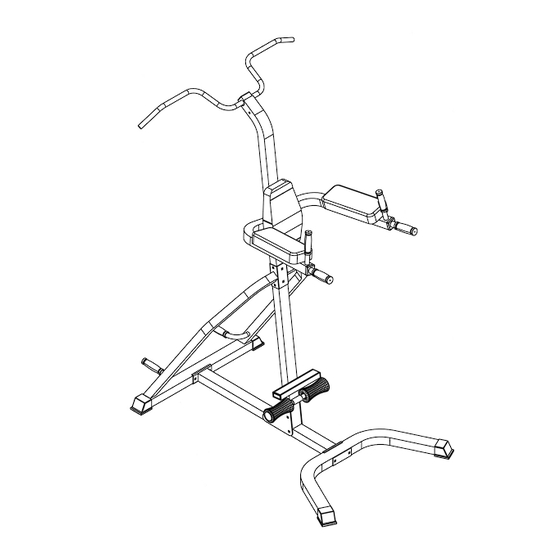
Page 5: Assembly Instruction
ASSEMBLY INSTRUCTION Tools Required to Assemble the Machine: Two Adjustable Wrenches and Allen Wrenches NOTE: It is strongly recommended this machine be assembled by two or more people to avoid possible injury. STEP 1 (See Diagram 1) A.) Connect the Front Stabilizer (#1) to the Base Frame (#3). Secure it with two M10 x 3 ¾” Carriage Bolts (#27), one Bracket (#14), two ¾”... - Page 6 STEP 2 (See Diagram 2) A.) Attach Left Support Frame (#6) onto the Rear Stabilizer (#2). Secure it with a M10 x 2 ½” Allen Bolt (#30) and ¾” Washer (#35) from the bottom up. Repeat the same step to install the Right Support Frame (#7) to the Rear Stabilizer.
- Page 7 STEP 3 (See Diagram 3) A.) Attach the Left Dip Support (#8) and Right Dip Support (#9) to the Upper Vertical Frame (#5). Secure them with two M10 x 3 ¾” Carriage Bolts (#27), ¾” Washers (#35), and M10 Aircraft Nuts (#36).
- Page 8 STEP 4 (See Diagram 4) A.) Attach Backrest Pad (#16) to the Upper Vertical Frame (#5). Secure it with two M8 x 2 ¾” Allen Bolts (#32) and 5/8” Washers (#34). B.) Insert the Chin-up Bar (#10) into the top opening on the Upper Vertical Frame (#5). Secure it with one M10 x 3 ¼”...
-
Page 10: Parts List
Parts list KEY NO. DESCRIPTION Q’ty Front Stabilizer Rear Stabilizer Base Frame Lower Vertical Frame Upper Vertical Frame Left Support Frame Right Support Frame Left Dip Support Right Dip Support Chin Up Bar Vertical Handle Foam Roll Tube Triangle Bracket Bracket Arm Pad Backrest Pad... -
Page 11: Limited Warranty
IMPEX INC. LIMITED WARRANTY IMPEX Inc. ("IMPEX") warrants this product to be free from defects in workmanship and material, under normal use and service conditions, for a period of two years on the Frame from the date of purchase. This warranty extends only to the original purchaser. IMPEX's obligation under this Warranty is limited to replacing or repairing, at IMPEX's option.
Need help?
Do you have a question about the TC-3001 and is the answer not in the manual?
Questions and answers