Table of Contents
Advertisement
For more information, visit www.desatech.com
For more information, visit www.desatech.com
100,000 140,000 and 200,000 Btu/Hr Variable Output with Thermostat
IMPORTANT: Read and understand this manual before assembling, starting or servicing
heater. Improper use of heater can cause serious injury. Keep this manual for future reference.
TABLE OF CONTENTS
SAFETY INFORMATION ............................................................ 2
PRODUCT IDENTIFICATION ..................................................... 3
UNPACKING ............................................................................... 3
FUELS ......................................................................................... 3
VENTILATION ............................................................................. 3
THEORY OF OPERATION ......................................................... 4
ASSEMBLY ................................................................................. 4
OPERATION ............................................................................... 5
OPERATION WITH PORTABLE GENERATOR .......................... 6
STORING, TRANSPORTING, OR SHIPPING ............................ 7
PREVENTATIVE MAINTENANCE SCHEDULE ......................... 7
Fill In For Your Records
Model No. ___________________
(Located on side panel)
Serial No. ___________________
(Located on fuel tank)
Date of Purchase: ______________
Heater Sizes:
125,000 and 170,000 Btu/Hr Thermostat
Save this manual for future reference.
Save this manual for future reference.
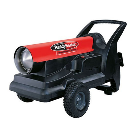
PORTABLE FORCED
AIR HEATERS
TM
OWNER'S MANUAL
TROUBLESHOOTING ................................................................ 8
SERVICE PROCEDURES .......................................................... 9
SPECIFICATIONS .................................................................... 17
WIRING DIAGRAMS ................................................................. 17
ILLUSTRATED PARTS BREAKDOWN AND PARTS LIST ....... 18
WHEELS AND HANDLE PARTS LIST ...................................... 24
TECHNICAL SERVICE ............................................................. 25
REPLACEMENT PARTS .......................................................... 25
ACCESSORIES ........................................................................ 25
WARRANTY AND REPAIR SERVICE ........................ Back Cover
®
Advertisement
Table of Contents

Related Manuals for Desa 125,000 Btu/Hr


Summary of Contents for Desa 125,000 Btu/Hr
-
Page 1: Table Of Contents
PORTABLE FORCED AIR HEATERS OWNER’S MANUAL For more information, visit www.desatech.com For more information, visit www.desatech.com Heater Sizes: 125,000 and 170,000 Btu/Hr Thermostat 100,000 140,000 and 200,000 Btu/Hr Variable Output with Thermostat IMPORTANT: Read and understand this manual before assembling, starting or servicing heater. -
Page 2: Safety Information
SAFETY INFORMATION SAFETY INFORMATION WARNINGS • Heater must be grounded. Use only a properly grounded three- IMPORTANT: Read this owner’s manual carefully and wire extension cord. Plug into grounded outlet only. completely before trying to assemble, operate, or ser- • Use only in areas free of flammable vapors or high dust content. -
Page 3: Product Identification
PRODUCT IDENTIFICATION UNPACKING FUELS VENTILATION PRODUCT IDENTIFICATION UNPACKING 1. Remove all packing items applied to heater for shipment. Handle Heat Output Knob Upper Shell 2. Remove all items from carton. Hot Air Thermostat Knob Outlet 3. Check items for any shipping damage. If heater is damaged, promptly inform dealer where you bought heater. -
Page 4: Theory Of Operation
THEORY OF OPERATION ASSEMBLY THEORY OF OPERATION ASSEMBLY The air pump forces air through the air line. The The Fuel System: air is then pushed through the nozzle. This air causes fuel to be lifted These models are furnished with wheels and a rear handle. Wheels, from the tank. -
Page 5: Operation
OPERATION OPERATION OPERATION (Thermostat Models) (Variable Output with Thermostat Models) IMPORTANT: Review and understand the warnings in the Safety Information section, page 2. They are IMPORTANT: Review and understand the warnings needed to safely operate this heater. Follow all local in the Safety Information section, page 2. -
Page 6: Operation With Portable Generator
OPERATION OPERATION WITH PORTABLE GENERATOR OPERATION (Variable Output with Thermostat Models) Continued Automatic Mode of Operation TO STOP HEATER Set the HEAT OUTPUT Knob to the AUTO setting. Push ON/OFF switch to the OFF (O) position. Set the THERMOSTAT Knob to the desired temperature. TO RESET HEATER Push ON/OFF switch to the ON (|) position. -
Page 7: Storing, Transporting, Or Shipping
STORING, TRANSPORTING, OR SHIPPING PREVENTATIVE MAINTENANCE SCHEDULE STORING, TRANSPORTING, OR SHIPPING Note: If shipping, transport companies require fuel tanks to be empty. 1. Remove drain plug from bottom side of fuel tank and drain all fuel. Replace drain plug. If any debris is noted in old fuel, add 1 or 2 quarts of clean kerosene to tank, stir, and drain again. -
Page 8: Troubleshooting
TROUBLESHOOTING TROUBLESHOOTING WARNING: Never service heater while it is plugged in, operating, or hot. Severe burns and electrical shock can occur. FAULT CONDITION POSSIBLE CAUSE REMEDY Motor does not start five seconds after 1. No power to heater 1. Check circuit breaker in electrical panel heater is plugged in 2. -
Page 9: Service Procedures
SERVICE PROCEDURES SERVICE PROCEDURES Setscrew WARNING: To avoid risk of burn and electrical Motor shock, never attempt to service heater while it is Setscrew plugged in, operating, or hot. UPPER SHELL REMOVAL Flush Remove screws along each side of heater using phillips screw- driver. - Page 10 SERVICE PROCEDURES SERVICE PROCEDURES Continued PUMP PRESSURE ADJUSTMENT FUEL FILTER Remove fan guard. 1. Remove control cover screws using 5/16" nut-driver. Remove pressure gauge plug from filter end cover (see Figure 10). 2. Remove control cover. Install accessory pressure gauge (part number HA1180). 3.
- Page 11 SERVICE PROCEDURES SERVICE PROCEDURES Continued (For 200VT Model Only) FUEL VALVE (For 200VT Model Only) Remove control cover screws using phillips screwdriver. 1. Remove control cover (see Figure 13) and upper shell (see Remove control cover (see Figure 13). Figure 6, page 9) screws using phillips screwdriver. Pull lower fuel line off the fuel valve fitting (see Figure 13).
- Page 12 SERVICE PROCEDURES SERVICE PROCEDURES Continued IGNITOR Remove upper shell (See Upper Shell Removal, page 9). 8. Carefully remove replacement ignitor from styrofoam packing. Remove fan (see page 9). 9. Carefully guide ignitor into opening in nozzle adapter bracket. Do not strike ignitor element. Attach ignitor to nozzle adapter Remove 2 control cover screws with a phillips screwdriver.
- Page 13 SERVICE PROCEDURES SERVICE PROCEDURES Continued NOZZLE ASSEMBLY (For 125T/170T/100VT/140VT Models Only) Combustion Remove upper shell (see Upper Shell Removal, page 9). Nozzle/Adapter Chamber Assembly Remove fan (see Fan, page 9). Remove fuel and air line hoses from nozzle assembly (see Fig- ure 17).
- Page 14 SERVICE PROCEDURES SERVICE PROCEDURES Continued (For 200VT Model Only) FUEL AND AIR LINE REPLACEMENT AND PROPER ROUTING Remove combustion chamber and ignitor by following steps 1 through 7 under Ignitor, page 12. Remove upper shell (see Upper Shell Removal, page 9). Carefully place the ignitor in a safe location.
- Page 15 SERVICE PROCEDURES SERVICE PROCEDURES Continued PUMP ROTOR Blade (Procedure if Rotor is Binding) Pump Plate Remove upper shell (see Upper Shell Removal, page 9). 2. Remove fan guard. Air Intake Filter Remove filter end cover screws using 5/16" nut driver (see Fig- Filter End ure 23).
- Page 16 SERVICE PROCEDURES SERVICE PROCEDURES Continued IGNITION CONTROL ASSEMBLY IGNITION CONTROL ASSEMBLY (Thermostat Models) (Variable Output with Thermostat Models) WARNING: High voltage! WARNING: High voltage! 1. Unplug heater. Unplug heater. 2. Remove control cover screws (2) using phillips screwdriver to Remove control cover screws (2) using phillips screwdriver to expose ignition control assembly.
-
Page 17: Specifications
SPECIFICATIONS WIRING DIAGRAMS SPECIFICATIONS Model Size 125T 170T 100VT 140VT 200VT Output Rating (Btu/Hr) 125,000 170,000 65,000-100,000 100,000-140,000 140,000-200,000 Fuel Use only kerosene, #1/#2 diesel/fuel oil, JET A or JP-8 fuels* Fuel Tank Capacity (U.S. Gal./Liters) 13.5/51 13.5/51 13.5/51 13.5/51 13.5/51 Fuel Consumption (Gal. -
Page 18: Illustrated Parts Breakdown And Parts List
ILLUSTRATED PARTS BREAKDOWN 125T and 170T Models ILLUSTRATED PARTS BREAKDOWN 125T and 170T MODELS 10-1 10-2 10-3 10-4 10-5 10-6 10-17 10-7 10-16 10-8 10-15 10-9 10-13 10-10 10-14 10-11 10-13 10-12 Motor and Pump Assembly For more information, visit www.desatech.com For more information, visit www.desatech.com 108481... - Page 19 PARTS LIST 125T and 170T Models PARTS LIST 125T and 170T MODELS This list contains replaceable parts used in your heater. When ordering parts, be sure to provide the correct model and serial numbers (from the model plate), then the part number and descrip- tion of the desired part.
- Page 20 ILLUSTRATED PARTS BREAKDOWN 100VT and 140VT Models ILLUSTRATED PARTS BREAKDOWN 100VT and 140VT MODELS 10-1 10-2 10-3 10-4 10-5 10-6 10-15 10-7 10-14 10-8 10-13 10-9 10-11 10-12 10-11 10-10 Motor and Pump Assembly For more information, visit www.desatech.com For more information, visit www.desatech.com 108481...
- Page 21 PARTS LIST 100VT and 140VT Models PARTS LIST 100VT and 140VT MODELS This list contains replaceable parts used in your heater. When ordering parts, be sure to provide the correct model and serial numbers (from the model plate), then the part number and description of the desired part. PART PART NUMBER...
- Page 22 ILLUSTRATED PARTS BREAKDOWN 200VT Model ILLUSTRATED PARTS BREAKDOWN 200VT MODEL 7-10 7-11 Nozzle Assembly 10-1 10-2 10-3 10-4 10-5 10-6 10-16 39-1 10-7 39-4 10-15 39-6 10-8 39-5 10-14 10-9 10-13 10-12 39-4 10-11 39-2 10-10 Motor and Pump Assembly 39-3 Fuel Valve Assembly For more information, visit www.desatech.com...
- Page 23 PARTS LIST 200VT Model This list contains replaceable parts used in your heater. When ordering parts, be sure to provide the correct PARTS LIST model and serial numbers (from the model plate), then the part number and description of the desired part. 200VT MODEL PART PART...
-
Page 24: Wheels And Handle Parts List
WHEELS AND HANDLE WHEELS AND HANDLE WHEELS AND HANDLE PARTS LIST PART PART NUMBER DESCRIPTION QTY. 108459-01 Handle/Support WP 4C Washer 108630-01 Screw 108463-01 Extension Cord Wrap 108466-01 Axle 108468-01 Washer 107426-01 Wheel Kit C3-8C Cotter Pin For more information, visit www.desatech.com For more information, visit www.desatech.com 108481... -
Page 25: Technical Service
TECHNICAL SERVICE REPLACEMENT PARTS ACCESSORIES TECHNICAL SERVICE ACCESSORIES Purchase accessories and parts from your nearest dealer or service You may have further questions about installation, operation, or center. If they can not supply these accessories or parts, either contact troubleshooting. your nearest parts dealer or DESA International at 1-866-672-6040 If so, contact DESA International’s Technical Service Department for referral information. -
Page 26: Warranty And Repair Service
WARRANTY AND REPAIR SERVICE LIMITED WARRANTY DESA International warrants this product and any parts thereof, to be free from defects in materials and workmanship for two (2) years from the date of first purchase when operated and maintained in accordance with instructions. This warranty is extended only to the original retail purchaser, when proof of purchase is provided.
Need help?
Do you have a question about the 125,000 Btu/Hr and is the answer not in the manual?
Questions and answers