Williams 4007332 Owner's Manual
Counterflow direct-vent gas wall furnaces
Hide thumbs
Also See for 4007332:
- Owner's manual (48 pages) ,
- Brochure & specs (2 pages) ,
- Owner's manual (48 pages)
Table of Contents
Advertisement
Owner‟s Manual
WARNING: This direct-vent furnace is approved for aftermarket mobile home installations (once the mobile home is
sold, installed and stationary) unless prohibited by local codes. Not for mobile home manufacturer (factory) installation.
Do not install any of these furnaces (natural or L.P. Gas) in trailers or recreational vehicles.
Williams Furnace Co. 250 West Laurel Street Colton, California 92324 U.S.A.
S
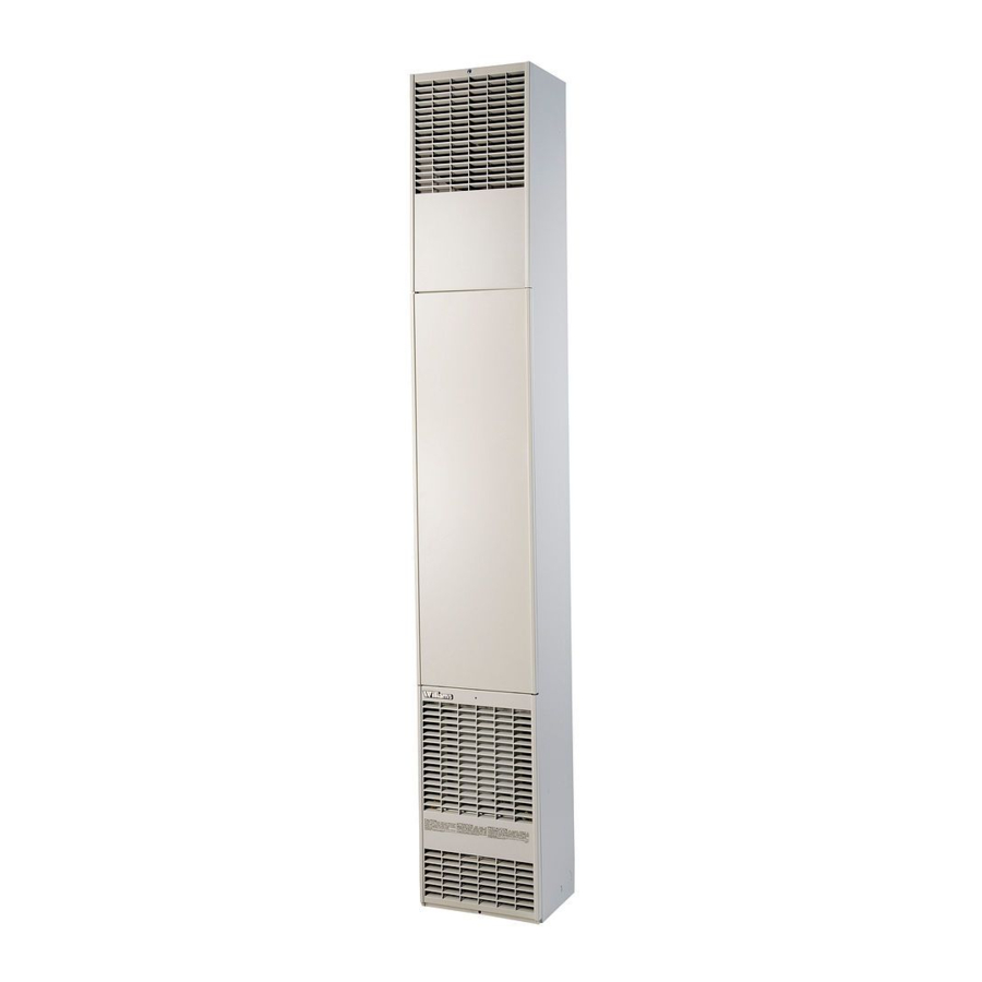
Counterflow Direct-Vent
Gas Wall Furnaces
Model Numbers:
4007332; 4007732; 5507332; 6007732
FOR USE WITH NATURAL GAS ONLY
Model Numbers:
4007331; 4007731; 5507331; 6007731
FOR USE WITH LIQUEFIED PETROLEUM (L.P.) GAS ONLY
READ THIS OWNER‟S MANUAL CAREFULLY BEFORE YOU
INSTALL YOUR NEW WILLIAMS WALL FURNACE.
WARNING:
If
the
instructions is not followed exactly, a fire or
explosion
may
damage, personal injury or loss of life.
Do not store or use gasoline or other
flammable vapors and liquids in the vicinity
of this or any other appliance.
WHAT TO DO IF YOU SMELL GAS:
Open all windows.
Do not try to light any appliance.
Do not touch any electrical switch; do not
use any phone or cell phone in your
building.
Extinguish any open flame.
Immediately call your gas supplier from
a neighbor‟s phone. Follow the gas
supplier‟s instructions.
If you cannot reach the gas supplier,
call the fire department.
Installation and service must be performed
by a qualified installer, service agency or
the gas supplier.
WARNING: Improper installation, adjustment, alteration,
service or maintenance can cause injury or property
damage. Refer to this manual. For assistance or for
additional information consult a qualified installer,
service agency or the gas supplier.
ave this manual for future reference.
information
in
these
result
causing
property
Advertisement
Table of Contents
Troubleshooting

Related Manuals for Williams 4007332


Summary of Contents for Williams 4007332
- Page 1 Not for mobile home manufacturer (factory) installation. Do not install any of these furnaces (natural or L.P. Gas) in trailers or recreational vehicles. Williams Furnace Co. 250 West Laurel Street Colton, California 92324 U.S.A.
-
Page 2: Your Williams Warranty
Warranty & Installation Record – 2 Warranty The manufacturer, Williams Furnace Co., warrants this wall furnace or heater to the original purchaser under the following conditions: LIMITED ONE-YEAR WARRANTY 1. Any part thereof which proves to be defective in material or workmanship within one year from date of original purchase for use will be replaced at the Manufacturer‟s option, FOB to its factory. -
Page 3: Table Of Contents
Installation Record ................. 2 Table of Contents ................3 Unpack the furnace ............... 6 Safety Rules .................. 4 Learn how to unpack the new Williams Furnace and verify that all its parts are in working order. Introduction ................5-6 Basic Description ................5 Install the furnace.............. -
Page 4: Safety Rules
Safety Rules Install the furnace vent directly to the outdoors so that harmful combustible flue gases will not collect inside the WARNING: Read these rules and the instructions building. Follow the venting instructions for your type of carefully. Failure to follow these rules and installation exactly. -
Page 5: Introduction
This was done to assure you of receiving the best value and most reliable appliance of its type available today. We are confident that your Williams furnace can provide you years of low cost, efficient, heating comfort. Thank you for purchasing a Williams furnace. -
Page 6: Optional Accessories
Introduction Optional Accessories Let‟s you route some heated air to side of furnace in the same SIDE OUTLET GRILLE KIT 6701 room. See pages 7 and 10. Let‟s you route some heated air into a second room. Mounts on the side wall of second room and must be within 10 inches of wall TRIM STRIP KIT 4701 furnace. -
Page 7: Installing Your Wall Furnace
Installing Your Furnace 1. Locate the furnace properly within the space to be heated. The following steps are needed for proper installation and safe operation of your furnace. If you have any doubts as to any 2. Install the furnace in accordance with local codes or requirements, always consult your local Heating or Plumbing ordinances and instructions provided. -
Page 8: Installing Your Furnace
Installing Your Furnace FIGURE 4 11. Be sure to provide adequate clearance and service access. The front of the furnace must face the open room. VENT CAP 12. Choose a location for the thermostat about 5-feet above the floor on an inside wall. The thermostat wire supplied with your furnace is 20-feet long, which should be enough to run up through the attic of a single-story home, so the thermostat can be a maximum of 16-feet from the furnace measure in a... -
Page 9: Recessed Mount Installation
Installing Your Furnace Recessed Mount Installation FIND THE STUDS FIGURE 8 Wall Opening for Recessed Mount Use a stud locator or small finishing nails. Repeatedly drive and remove a nail into the wall in the area of the stud until you find it. Then find one side. - Page 10 Installing Your Furnace FIGURE 10 Gas & Electrical Openings GAS AND ELECTRICAL SUPPLY OPENINGS Holes must be drilled for the gas line and electrical supply. Holes must be located from each side of furnace as shown in Fig. 10. Decide whether the gas line will come through the floor or wall. Drill a 1½...
-
Page 11: Surface Mount Installation
Installing Your Furnace Surface Mount Installation FIND THE STUDS ROUGH-IN OPTIONAL SIDE OUTLET NO. 6701 1. Find two studs at spot where furnace is to be placed. Use a Install plaster ground as shown in Figs. 12 & 13. Flanges of plaster ground extend the thickness of normal plaster. - Page 12 Installing Your Furnace MOUNTING OPTIONAL SIDE OUTLET GRILLE KIT OPTIONAL 2-WAY DIFFUSING GRILLE KIT NO. 6703 NO. 6701 Refer to Fig. 15. Refer to Fig. 14. CAUTION: For use only in conjunction with a front 1. Before setting furnace into position, cut 5 rectangular "...
-
Page 13: Thermostat Installation
Installing Your Furnace Thermostat Installation 1. If an old thermostat is being replaced and is in a satisfactory FIGURE 16 Route Thermostat Cable location and the wiring appears to be in good condition, use existing wiring. If in doubt, use new wire. 2. -
Page 14: Vent Installation
Installing Your Furnace Vent Installation WARNING: DANGER OF PROPERY DAMAGE, BODILY INJURY OR DEATH. FIGURE 18 Wall Thickness Proper vent installation is critical to the safe operation of the furnace. Therefore, carefully read and follow all the instructions given in this section. WALL The following instructions are for either surface or recess mounted WITH... -
Page 15: Trim
Installing Your Furnace FIGURE 19 Vent Installation NOTE: Each tube must overlap the collars of the vent cap a minimum of 1¼-inches, which is obtained when tubes are cut correctly as previously described. 5507332 6007732 5507332 6007731 Trim To conceal the space between the furnace and wall, use 4701 Trip 2. -
Page 16: Mounting Your Furnace
3. Be sure the gas is shut off at the meter. and up. 4. Before placing the furnace in position, remove the gas piping MODELS: 4007332, 5507332 stub if necessary to locate the furnace. 4007331, 5507331 5. After installing the vent tubes, carefully move the furnace into position, being sure not to bend the vent tubes. - Page 17 Installing Your Furnace FASTEN FURNACE TOP (SURFACE MOUNTING) Fasten the furnace top to wall using two (2) metal anchors FIGURE 22 Burner Pan (packed in plastic bag with thermostat) by placing them over the back flange of the furnace top and screwing them to the wall. Refer to Fig.
-
Page 18: Gas Supply And Piping
Installing Your Furnace Gas Supply and Piping The gas control valve within the furnace, is shipped with a seal over the gas inlet tapping. Do not remove seal until ready to connect piping. FIGURE 24 WARNING: Danger of property damage, bodily injury or death. -
Page 19: Electrical Wiring
Installing Your Furnace The following rules apply: disconnected during testing. (SEE WARNING) Apply soap solution to each joint. Bubbles forming indicate a leak. Correct 1. Use new, properly reamed pipe free from metal chips and even the slightest leak at once. debris such as steel or black iron pipe. - Page 20 Installing Your Furnace GROUNDING WALL THERMOSTAT WIRING The appliance when installed must be electrically grounded in accordance with local codes and ordinances or in their absence, Run thermostat wire to the furnace. Connect thermostat to the two with National Electrical Code (ANSI/NFPA 70) or Canadian wires marked "Thermostat"...
-
Page 21: Start Up Procedure
Installing Your Furnace Start-Up Procedure Start furnace using the procedures in the section CHECK THE GAS INPUT (NATURAL GAS ONLY) “OPERATING YOUR FURNACE”. WARNING: Natural gas heating value (Btu per cubic foot) can vary significantly. Therefore, it is WARNING: Danger of bodily injury or death. the installer's responsibility to see that Btu/hr. -
Page 22: Operating Your Furnace
Operating Your Furnace Operating Your Furnace For models equipped with WILLIAMS gas valve P321704 or STANDING PILOT MODELS P321705. 4007732; 6007732; 4007731; 6007731 Models are equipped with a two-rate control valve. The rate knob NOTE: on the gas valve is marked "LO" and "HI." Turn the rate knob to For models equipped with WILLIAMS gas valve P322041 or the "LO"... -
Page 23: Lighting Instructions
Care – 23 Operating Your Furnace FOR YOUR SAFETY, READ BEFORE LIGHTING • If you cannot reach your gas supplier, call the fire department. WARNING: If you do not follow these instructions Use only your hand to push in or turn the gas control knob. exactly, a fire or explosion may result causing Never use tools. - Page 24 Operating Your Furnace FOR YOUR SAFETY, READ BEFORE LIGHTING • If you cannot reach your gas supplier, call the fire department. WARNING: If you do not follow these instructions Use only your hand to push in or turn the gas control knob. exactly, a fire or explosion may result causing Never use tools.
- Page 25 Do not operate the furnace with a broken or NOTE: missing pilot observation door. For models equipped with WILLIAMS gas valve P322043 or P322044 refer to this page and Page 26 for "SAFETY & LIGHTING INSTRUCTION" and "TURN GAS OFF TO APPLIANCE."...
- Page 26 Operating Your Furnace FOR YOUR SAFETY, READ BEFORE LIGHTING • If you cannot reach your gas supplier, call the fire department. WARNING: If you do not follow these instructions Use only your hand to push in or turn the gas control knob. exactly, a fire or explosion may result causing Never use tools.
- Page 27 Care – 27 Operating Your Furnace FOR YOUR SAFETY, READ BEFORE LIGHTING • If you cannot reach your gas supplier, call the fire department. WARNING: If you do not follow these instructions Use only your hand to push in or turn the gas control knob. exactly, a fire or explosion may result causing Never use tools.
-
Page 28: How To Care For Your Furnace
Caring for Your Furnace How To Care For Your Furnace The pilot flame should surround the thermocouple tip 5/8 to 1/2- WARNING: Danger of bodily injury or death. Turn inch. Refer to Page 29, Fig. 30. If the flame needs adjusting, do it off electric power supply at the disconnect switch, as follows: fuse box or service panel before removing any... -
Page 29: Furnace Technical Information
(Fig. 30), for the ignition device to function properly. Furnace Technical information Furnace Technical Information ** Rating in Btu/hr. Main Burner Orifice Model Gas Type Number DRILL DEC. QTY. Input CAPAC. 4007332 NATURAL .1160 40,000 31,732 4007331 L.P. .0760 40,000 32,356 4007732 NATURAL .1160 40,000... -
Page 30: Wiring Diagrams
Wiring Diagrams Wiring Diagrams MODELS - 4007332 /4007331 MODELS - 5507332 /5507331 FOR 40M Btu/hr. FAN TYPE VENTED WALL FURNACE FOR 55M Btu/hr. FAN TYPE VENTED WALL FURNACE WITH INTERMITTENT IGNITION CONTROL SYSTEM WITH INTERMITTENT IGNITION CONTROL SYSTEM... -
Page 31: Wiring Diagrams
Accessories– 31 Wiring Diagrams MODELS - 4007732/4007731 MODELS - 6007732/6007731 FOR 40M Btu/hr. FAN TYPE VENTED WALL FURNACE FOR 60M Btu/hr. FAN TYPE VENTED WALL FURNACE WITH STANDING PILOT CONTROL SYSTEM WITH STANDING PILOT CONTROL SYSTEM... -
Page 32: Repair Parts 4007332, 4007732, 4007331 & 4007731
Replacements Parts... - Page 33 Replacements Parts...
-
Page 34: Parts List For 4007332, 4007732, 4007331 & 4007731
Replacements Parts REPLACEMENT PARTS LIST FOR MODELS 4007332; 4007732; 4007331 and 4007731 PART NO. FOR MODEL Ref. Description Number 4007332 4007732 4007331 4007731 Outer Casing with Air Pan 11C42-2 11C42-2 11C42-2 11C42-2 Heating Element 11C67 11C67 11C67 11C67 Element Tube... - Page 35 Replacements Parts REPLACEMENT PARTS LIST FOR MODELS 4007332; 4007732; 4007331 and 4007731 Ref. PART NO. FOR MODEL Description Number 4007332 4007732 4007331 4007731 Manifold P323653 P323653 P323653 P323653 Manifold Gasket P151700 P151700 P151700 P151700 Orifice Fitting, Specify Model & Gas...
-
Page 36: Repair Parts 5507332, 6007732, 5507331 & 6007731
Replacements Parts... - Page 37 Replacements Parts 6007732 and 6007731...
- Page 38 Replacements Parts 6007732 & 6007731...
-
Page 39: Parts List For 5507332, 6007732, 5507331 & 6007731
Replacements Parts REPLACEMENT PARTS LIST FOR MODELS 5507332 and 5507331 PART NO. FOR MODEL Ref. Description Number 5507332 5507331 Outer Casing with Air Pan 11C42-1 11C42-1 Heating Element 11C66 11C66 Element Tube 11C37 11C37 Inner Liner 7B79 7B79 Deflector Baffle Handle 11C63 11C63 Fan Shroud... - Page 40 Replacements Parts REPLACEMENT PARTS LIST FOR MODELS 5507332, 6007732, 5507331 and 6007731 PART NO. FOR MODEL Ref. Description Number 5507332 6007732 5507331 6007731 Manifold P323654 P323654 P323654 P323654 Manifold Gasket P151700 P151700 P151700 P151700 Orifice Fitting, Specify Model & Gas P090541 P090538 P090552...
- Page 41 Replacements Parts REPLACEMENT PARTS LIST FOR MODELS 6007732 and 6007731 PART NO. FOR MODEL Ref. Description Number 6007732 6007731 Outer Casing with Air Pan 11C42-1 11C42-1 Air Pan Tunnel Gasket P151900 P151900 Inner Liner 11B120 11B120 Heating Element 11C66 11C66 Peep Hole Cover 12B40 12B40...
-
Page 42: Installations In The State Of Massachusetts
Installations in the State of Massachusetts All installations in the State of Massachusetts must use the following requirements when installing, maintaining or operating direct-vent propane or natural gas-fired space heaters. For direct-vent appliances, mechanical-vent heating appliances or domestic hot water equipment, where the bottom of the vent terminal and the air intake is installed below four feet above grade the following requirements must be satisfied: 1. -
Page 43: Forsaire Hardwire Accessory - 9940
WARNING: Danger of bodily injury. Turn off electric power supply at disconnect switch, fuse box or service panel before working on the furnace. SUMMARY: This accessory converts Williams' Forsaire Counterflow furnaces using the electric service cord provided, to a hardwired, permanent electrical connection. - Page 44 Troubleshooting TROUBLESHOOTING CHART FOR Models FOR MODELS: 4007732; 6007732; 4007731; 6007731 *Also applicable to Models equipped with an electric intermittent pilot system. (Continued on next page) SYMPTOM POSSIBLE CAUSE CORRECTIVE ACTION Check pilot flame – it must impinge on the thermocouple. The pilot flame may be low Thermocouple producing or blowing (high) causing pilot to drop out.
-
Page 45: Troubleshooting
Care – 45 Troubleshooting SYMPTOM POSSIBLE CAUSE CORRECTIVE ACTION 4. Burner comes "ON", blower comes "ON", Furnace not operating at Check for low gas pressure at gas valve - should be 4" W.C. for Natural Gas, 11" W.C. cycles "ON" full rate. -
Page 46: Troubleshooting Chart
Troubleshooting TROUBLESHOOTING CHART FOR MODELS FOR MODELS: 4007332; 5507332; 4007331; 5507331 NOTE: Before troubleshooting the intermittent pilot system, be sure thermostat is turned to highest setting, gas shut-off valve and gas valve knob are in the ON position, and electric power is turned ON the furnace. Follow all steps in sequence. A volt-ohm meter will be needed to satisfactorily determine if any components are malfunctioning. - Page 47 Care – 47 Troubleshooting SYMPTOM POSSIBLE CAUSE CORRECTIVE ACTION NOTE: Wait at least 90 seconds after pilot lights before doing the check out procedures for problem number 4. With the thermostat ON, be sure that the pilot and sensor are properly aligned so that the pilot flame impinges the top 5/8 inch of the sensor.
-
Page 48: Hints And Information
3. PART NUMBER 4. PART DESCRIPTION All parts listed herein may be ordered from your equipment supplier. The Model Number of your Williams wall furnace will be found on the nameplate near gas valve, inside control compartment. Williams Furnace Company • 250 West Laurel Street, Colton, CA 92324 ...
Need help?
Do you have a question about the 4007332 and is the answer not in the manual?
Questions and answers