Table of Contents
Advertisement
Available languages
Available languages
Quick Links
Download this manual
See also:
Owner's Manual
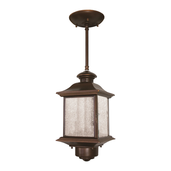
Motion Sensing
Pendant Light
Model 4350
1
8
9
Be sure to remove all contents from packaging and verify all items are present before assembling this
light fixture. This package includes the following items:
1 - Canopy Screws (x3)
2 - Universal Mounting Bracket
3 - Mounting Bracket Screws
(x2)
4 - Nut
5 - Star Washer
6 - S-Hanger Terminal
7 - Flat Washer
8 - Canopy
© 2006 DESA Specialty Products™
Junction Box
(Not Included)
2
3
4
5
6
7
9 - Knurled Canopy Nuts (x3)
10 - Decorative Flat Washer
11 - Small, Thick, Decorative
Washer
12 - 1"
Rod
13 - Mounting Rods (x3)
- 6" (15.2 cm) Rod
- 12" (30.5 cm) Rod (x2)
• Light comes on when motion is detected.
• Automatically turns light off.
• Optional half power accent lighting.
• Photocell keeps the light off during daylight
hours.
• Hinged door for easy bulb access.
10
11
12
13
(25.4 mm) Threaded
FEATURES
®
IT E
B R
A L
D U
S K
W N
D U
D A
T O
6
3
F
O F
M IN
1 0
5
E
1
-T IM
S T
T E
O N
15
16
14 - Pendant Light Fixture
15 - Sensor Cover
16 - Smooth Sensor Cover
Screws (x4)
Other Items Not Shown:
- Wire Nuts (x3)
- Lens Shield (x2)
- S-Hanger
- Foam Tape
14
598-1219-04
Advertisement
Table of Contents

Related Manuals for Heath Zenith 4350


Summary of Contents for Heath Zenith 4350
- Page 1 Motion Sensing Pendant Light Model 4350 Be sure to remove all contents from packaging and verify all items are present before assembling this light fixture. This package includes the following items: 1 - Canopy Screws (x3) 2 - Universal Mounting Bracket...
-
Page 2: Operation
Before installation, record the model number listed inside the fixture. Attach receipt in case of possible warranty issues. Model Number: REQUIREMENTS • The Light Control requires 120 volts AC. • If you want to use Manual Mode, the control must be wired through a switch. - Page 3 INSTALL UNIVERSAL MOUNTING BRACKET WARNING: Turn power off at circuit breaker. 1. Remove universal mounting bracket from canopy by removing the 3 knurled canopy nuts. 2. Tighten the three canopy screws finger tight. 3. Attach universal mounting bracket to junction box securely with the two screws provided.
- Page 4 ASSEMBLE PENDANT LIGHT 1. Route light fixture wires through mounting rod (threaded end first) that will connect to the fixture. 2. Screw rod into light fixture. Tighten mounting rod securely. 3. Continue this process until desired number of mounting rods are connected to light fixture (including the rod connected to the canopy).
- Page 5 INSTALL PENDANT LIGHT TO JUNCTION BOX 1. Push wires into the junction box. 2. Remove S-Hanger. 3. Slide canopy onto canopy screws and tighten knurled canopy nuts securely against the canopy. Note: Canopy should fit tight against mounting surface. Canopy Screw Knurled Canopy Nut BULB INSTALLATION AND...
-
Page 6: Top View
5. Adjust the SENSITIVITY to increase or de- crease the range as needed. Too much sen- sitivity may cause false triggering due to heat sources in the coverage area (see Adjustment of Coverage Area or Troubleshooting section). IT Y IT IV –... -
Page 7: Specifications
2. Cut desired amount of foam tape needed to adhere the lens shield to the sensor lens. 3. Remove paper backing from one side of cut foam tape and adhere foam tape to inside of lens shield. 4. Remove paper backing from other side of cut foam tape and adhere lens shield to sensor lens. -
Page 8: Troubleshooting Guide
SYMPTOM POSSIBLE CAUSE Light will not 1. Light switch is turned off. come on. 2. Bulbs are loose or burned out. 3. Fuse is blown or circuit breaker is turned off. 4. Daylight turn-off is in effect (re- check after dark). 5. - Page 9 Lámpara colgante con detector de movimiento Modelo 4350 Asegúrese de retirar todo el contenido del paquete y verificar que todas las partes estén incluidas antes de ensamblar este artefacto de luz. Este paquete incluye las siguientes partes: 1 - Tornillos del escudete (x3)
-
Page 10: Modo Manual
Antes de instalar, registre el número del modelo mostrado dentro del aparato. Fije el recibo en caso posibles reclamos por la garantía. Número del modelo: REQUISITOS • El Control de Luz requiere 120 VCA. • Para usar el Sobrecontrol Manual, conecte el control con un interruptor. - Page 11 INSTALE LA CONSOLA UNIVERSAL DE MONTAJE ADVERTENCIA: Desconecte la energía en el disyuntor. 1. Retire del escudete la consola universal de montaje retirando las 3 tuercas estriadas del escudete. 2. Apriete a mano las tres tuercas del escudete. 3. Sujete bien la consola universal de montaje a la caja de empalmes con los dos tornillos provistos.
-
Page 12: Cableado Del Aparato De Luz
ENSAMBLE LA LÁMPARA COLGANTE 1. Pase los conductores del artefacto de luz a tra- vés de la varilla de montaje (primero el extremo roscado) que va a conectar al artefacto. 2. Enrosque la varilla en el artefacto de luz. Apriete bien la varilla de montaje. - Page 13 INSTALACIÓN DE LA LÁMPARA A LA CAJA DE EMPALMES 1. Empuje los conductores para meterlos en la caja de empalmes. 2. Retire la percha-S. 3. Deslice el escudete hasta ensartar con sus tornillos y apriete luego las tuercas estriadas contra el escudete. Nota: El escudete debe encajar apretadamente contra la superficie de montaje.
- Page 14 5. Regule la SENSIBILIDAD para aumentar o disminuir el margen según sea necesario. Dema- siada sensibilidad puede ocasionar activaciones falsas debido a fuentes de calor en las áreas de cobertura (Vea Regulación del área de cobertura o la sección Análisis de averías). IT Y IT IV –...
-
Page 15: Especificaciones
2. Corte la cantidad necesaria de cinta espumosa que necesita para adherir la cubierta a la placa traslúcida. 3. Retire el papel protector de un lado de la cinta espumosa y adhiérala al interior de la cubierta. 4. Retire el papel protector del otro lado de la cinta espumosa cortada y adhiera la cubierta a la placa traslúcida del detector. -
Page 16: Guia De Investigacion De Averias
GUIA DE INVESTIGACION DE AVERIAS SINTOMA POSIBLE CAUSA La luz no se 1. El interruptor de luz está apagado. enciende. 2. Las bombillas están flojas o que- madas. 3. El fusible está quemado o el cor- tacircuitos está apagado. 4. La desconexión de luz del día está... -
Page 17: Caractéristiques
Luminaire suspendu à détecteur de mouvement Modèle 4350 Videz complètement l’emballage et assurez-vous d’avoir en main tous les éléments avant de débuter l’assemblage du luminaire. L’emballage devrait comprendre : 1 - Vis de la monture (3) 2 - Support universel 3 - Vis du support universel (2) 4 - Écrou... - Page 18 Avant l’installation, inscrivez ici le numéro de modèle qui se trouve à l’intérieur de l’appareil. Joignez-y le reçu d’achat pour les réclamations sous garantie. Numéro de modèle : EXIGENCES • La commande d'éclairage nécessite une alimen- tation 120 volts c.a. •...
- Page 19 INSTALLATION DU SUPPORT UNIVERSEL MISE EN GARDE : Coupez le courant au niveau du disjoncteur. 1. Retirez le support universel de la monture en enlevant les trois écrous moletés. 2. Serrez les trois vis de la monture à la main. 3.
-
Page 20: Branchement Des Fils
ASSEMBLAGE DU LUMINAIRE SUSPENDU 1. Faites passer les fils d’alimentation dans la tige d’installation (en commençant par l’extrémité filetée) qui sera raccordée au luminaire. 2. Vissez la tige dans le luminaire en la serrant solidement. 3. Poursuivez cette opération jusqu’à ce que le nombre souhaité... - Page 21 FIXATION DU LUMINAIRE SUSPENDU À LA BOÎTE DE CONNEXION 1. Repoussez les fils à l’intérieur de la boîte de connexion. 2. Enlevez le support en S. 3. Insérez la monture sur les vis de monture, puis serrez solidement les écrous moletés contre la monture.
- Page 22 4. Réglez la SENSIBILITÉ pour augmenter ou réduire la portée du détecteur, au besoin. Une trop grande sensibilité peut entraîner des déclenchements intempestifs attribuables à la présence de source de chaleur dans la zone de couverture (consultez la section Réglage de la zone de couverture ou Guide de dépannage).
-
Page 23: Fiche Technique
2. Découpez la quantité de ruban-mousse néces- saire pour coller le protecteur sur la lentille du capteur. 3. Retirez la pellicule protectrice d’un côté du ruban-mousse, puis collez le ruban à l’intérieur du protecteur de lentille. 4. Retirez la pellicule protectrice de l’autre côté du ruban-mousse, puis collez-le sur le capteur de mouvement. -
Page 24: Guide De Dépannage
SYMPTÔME CAUSE POSSIBLE La lampe ne 1. L’interrupteur d’éclairage est en s’allume pas. position hors circuit. 2. Les ampoules sont lâches ou grillées. 3. Le fusible du circuit a sauté ou le disjoncteur est en position hors circuit. 4. La fonction de mise hors circuit à...
Need help?
Do you have a question about the 4350 and is the answer not in the manual?
Questions and answers