Table of Contents
Advertisement
Advertisement
Table of Contents

Related Manuals for Asus P7F-M WS


Summary of Contents for Asus P7F-M WS
- Page 1 P7F-M WS...
- Page 2 Product warranty or service will not be extended if: (1) the product is repaired, modified or altered, unless such repair, modification of alteration is authorized in writing by ASUS; or (2) the serial number of the product is defaced or missing.
-
Page 3: Table Of Contents
Contents Notices ......................vii Safety information ..................viii About this guide ..................ix Typography ....................x P7F-M WS specifications summary ............xi Chapter 1: Product introduction Welcome! ..................1-3 Package contents ................. 1-3 Serial number label ..............1-4 Special features ................1-4 1.4.1... - Page 4 Using the dual function power switch ......3-4 Chapter 4: BIOS setup Managing and updating your BIOS ..........4-3 4.1.1 ASUS EZ Flash 2 utility ........... 4-3 4.1.2 BUPDATER utility............4-4 4.1.3 ASUS CrashFree BIOS 3 utility ........4-6 BIOS setup program ..............4-7 4.2.1...
- Page 5 Boot Device Priority ............4-32 4.6.2 Boot Settings Configuration .......... 4-33 4.6.3 Security ................. 4-34 Tools menu ................. 4-36 4.7.1 ASUS EZ Flash 2 ............4-36 Exit menu ..................4-37 Chapter 5: RAID configuration Setting up RAID ................5-3 5.1.1 RAID definitions .............. 5-3 5.1.2...
- Page 6 Management applications and utilities installation ....6-13 6.4.1 Running the support DVD ..........6-13 6.4.2 Drivers menu ..............6-13 6.4.3 Utilities menu ..............6-14 6.4.4 Make disk menu ............6-14 6.4.5 Contact information ............6-14 Appendix: Reference information P7F-M WS block diagram ............A-3...
-
Page 7: Notices
Canadian Department of Communications. This class B digital apparatus complies with Canadian ICES-003. REACH Complying with the REACH (Registration, Evaluation, Authorization, and Restriction of Chemicals) regulatory framework, we published the chemical substances in our products at ASUS REACH website at http://green.asus.com/english/REACH.htm. -
Page 8: Safety Information
Safety information Electrical safety • To prevent electrical shock hazard, disconnect the power cable from the electrical outlet before relocating the system. • When adding or removing devices to or from the system, ensure that the power cables for the devices are unplugged before the signal cables are connected. -
Page 9: About This Guide
Refer to the following sources for additional information and for product and software updates. ASUS websites The ASUS website provides updated information on ASUS hardware and software products. Refer to the ASUS contact information. Optional documentation Your product package may include optional documentation, such as warranty flyers, that may have been added by your dealer. -
Page 10: Typography
Conventions used in this guide To make sure that you perform certain tasks properly, take note of the following symbols used throughout this manual. DANGER/WARNING: Information to prevent injury to yourself when trying to complete a task. CAUTION: Information to prevent damage to the components when trying to complete a task. -
Page 11: P7F-M Ws Specifications Summary
P7F-M WS specifications summary Model Name P7F-M WS Processor Support / System Bus 1 * Socket LGA1156 Quad Core Intel Xeon 3400 series Server Processor Quad Core Intel Core i7-800 series Desktop Processor Quad Core Intel Core i5-700 series Desktop... - Page 12 P7F-M WS specifications summary Rear I/O External Serial Port Connectors External USB Port RJ-45 PS/2 KB/Mouse Monitoring CPU Temperature FAN RPM Environment Operation temperature: 10℃—35℃ Non operation temperature: -40℃—70℃ Non operation humidity: 20%—90% (Non condensing) *Specifications are subject to change without notice.
-
Page 13: Chapter 1: Product Introduction
This chapter describes the motherboard features and the new technologies it supports. Product introduction... - Page 14 Chapter summary Welcome! ..................1-3 Package contents ................. 1-3 Serial number label ..............1-4 Special features ................1-4 ASUS P7F-M WS...
-
Page 15: Welcome
® The motherboard delivers a host of new features and latest technologies, making it another standout in the long line of ASUS quality motherboards! Before you start installing the motherboard, and hardware devices on it, check the items in your package with the list below. -
Page 16: Serial Number Label
Before requesting support from the ASUS Technical Support team, you must take note of the motherboard's serial number containing 13 characters xxS1xxxxxxxxx shown as the figure below. With the correct serial number of the product, ASUS Technical Support team members can then offer a quicker and satisfying solution to your problems. - Page 17 DDR3 memory support The P7F-M WS supports UDIMM and RDIMM DDR3 memory that features data transfer rates of 1333/1066 MHZ to meet the higher bandwidth requirements of server and workstation applications. The 2-channel DDR3 architecture boosts system performance, eliminating bottlenecks. Furthermore, the supply voltage for the memory is reduced from 1.8 V for DDR2 to just 1.5V for DDR3.
-
Page 18: Innovative Asus Features
Innovative ASUS features ASUS MIO Audio card Enjoy high-end sound quality! The ASUS MIO audio card is a discrete 8-channel high definition audio (High Definition Audio previously codenamed Azalia) CODEC enable clearest high quality audio output, jack-sensing feature, retasking functions, and multi-streaming technology that simultaneously send different audio streams to different destinations. -
Page 19: Chapter 2: Hardware Information
This chapter lists the hardware setup procedures that you have to perform when installing system components. It includes description of the jumpers and connectors on the motherboard. Hardware information... - Page 20 Chapter summary Before you proceed ..............2-3 Motherboard overview ..............2-4 Central Processing Unit (CPU) ........... 2-8 System memory ................. 2-13 Expansion slots ................2-15 Jumpers ..................2-19 Connectors ................. 2-22 G.P. Diagnosis card installation (optional) ......2-29 ASUS P7F-M WS...
-
Page 21: Before You Proceed
ON, in sleep mode, or in soft-off mode. This is a reminder that you should shut down the system and unplug the power cable before removing or plugging in any motherboard component. The illustration below shows the location of the onboard LED ASUS P7F-M WS... -
Page 22: Motherboard Overview
Motherboard overview Before you install the motherboard, study the configuration of your chassis to ensure that the motherboard fits into it. To optimize the motherboard features, we highly recommend that you install it in an ATX 1.1 compliant chassis. Ensure to unplug the chassis power cord before installing or removing the motherboard. -
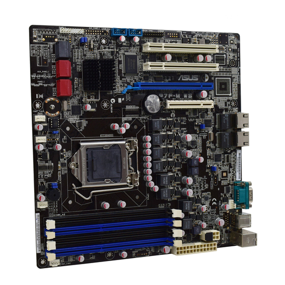
Page 23: Motherboard Layout
2.2.3 Motherboard layout ASUS P7F-M WS... -
Page 24: Layout Contents
2.2.4 Layout contents Slots/Soocket Page CPU sockets DDR3 sockets 2-13 PCI Express x16 slot (x16 link) 2-17 PCI Express x8 slot (x4 link) or MIO support 2-17 PCI slots 2-17 Jumpers Page Clear RTC RAM (CLRTC1) 2-19 CPU Fan and Chassis Fan control setting 2-20 (3-pin CPUFAN_SEL1, CHAFAN_SEL1) LAN controller setting (3-pin LAN_SW1, LAN_SW2) - Page 25 TPM connector (20-1 pin TPM) [Optional] 2-26 ATX power connectors (24-pin EATXPWR1, 8-pin EATX12V1) 2-26 System panel connector (20-1 pin PANEL1) 2-27 Front panel audio connector (10-1 pin AAFP) 2-28 Optical drive audio connector (4-pin CD) 2-28 ASUS P7F-M WS...
-
Page 26: Central Processing Unit (Cpu)
ASUS will shoulder the cost of repair only if the damage is shipment/transit-related. • Keep the cap after installing the motherboard. ASUS will process Return Merchandise Authorization (RMA) requests only if the motherboard comes with the cap on the LGA1156 socket. - Page 27 CPU notches. The CPU fits in only one correct orientation. DO NOT force the Gold CPU into the socket to prevent triangle bending the connectors on the mark socket and damaging the CPU! Alignment keys ASUS P7F-M WS...
- Page 28 Apply some Thermal Interface Material to the exposed area of the CPU that the heatsink will be in contact with, ensuring that it is spread in an even thin layer. Some heatsinks come with pre- applied thermal paste. If so, skip this step.
-
Page 29: Installing The Cpu Heatsink And Fan
Push down two fasteners at a time in a diagonal sequence to secure the heatsink and fan assembly in place. Orient the heatsink and fan assembly such that the CPU fan cable is closest to the CPU fan connector. ASUS P7F-M WS 2-11... -
Page 30: Uninstalling The Cpu Heatsink And Fan
Connect the CPU fan cable to the connector on the motherboard labeled CPU_FAN. DO NOT forget to connect the CPU fan connector! Hardware monitoring errors can occur if you fail to plug this connector. 2.3.3 Uninstalling the CPU heatsink and fan To uninstall the CPU heatsink and fan: Disconnect the CPU fan cable from the connector on the motherboard. -
Page 31: System Memory
Always install DIMMs with the same CAS latency. For optimum compatibility, it is recommended that you obtain memory modules from the same vendor. DO NOT combine RDIMM and UDIMM. • The motherboard supports x8 DRAM Only and x4 & x16 DRAM are not supported ASUS P7F-M WS 2-13... -
Page 32: Installing A Dimm
2.4.3 Installing a DIMM Unplug the power supply before adding or removing DIMMs or other system components. Failure to do so can cause severe damage to both the motherboard and the components. To install a DIMM: Press the retaining clips outward DDR3 DIMM notch to unlock a DIMM socket. -
Page 33: Expansion Slots
When using PCI cards on shared slots, ensure that the drivers support “Share IRQ” or that the cards do not need IRQ assignments. Otherwise, conflicts will arise between the two PCI groups, making the system unstable and the card inoperable. ASUS P7F-M WS 2-15... -
Page 34: Interrupt Assignments
2.5.3 Interrupt assignments Standard Interrupt assignments Priority Standard function System Timer Keyboard Controller Programmable Interrupt Communications Port (COM1) System CMOS/Real Time Clock ACPI Mode when used IRQ Holder for PCI Steering IRQ Holder for PCI Steering PS/2 Compatible Mouse Port Numeric Data Processor Primary IDE Channel Secondary IDE Channel... -
Page 35: Pci Express X16 Slot (X16 Link)
The PCI slot supports cards such as a LAN card, USB card, and other cards that comply with PCI 2.3 specifications. PCI_2 slot PCI_1 slot PCI Express x16 slot (x16 link) PCI Express x8 slot with MIO support (x4 link) ASUS P7F-M WS 2-17... -
Page 36: Connect Thermal Sensor Cable
2.5.7 Connect Thermal sensor cable Follow the steps below to connect the thermal sensor cable to the connector on your motherboard. Locate the TR1 connector on the motherboard. Connect the thermal sensor cable to the connector. Place the other end of the thermal sensor cable to the device you would like to monitor temperature. -
Page 37: Jumpers
Removing the cap will cause system boot failure! If the steps above do not help, remove the onboard battery and move the jumper again to clear the CMOS RTC RAM data. After the CMOS clearance, reinstall the battery. ASUS P7F-M WS 2-19... - Page 38 CPU Fan and Chassis Fan control setting (3-pin CPUFAN_SEL1, CHAFAN_SEL1) These jumpers allow you to switch for fan pin selection. The CPUFAN_SEL1 jumper is for the CPU fan control and the CHAFAN_SEL1 jumper is for the front fans and rear fans control. Set to pins 1–2 when using 4-pin fans or pins 2–3 when using 3-pin fans.
- Page 39 Insert the USB flash that contains the original or latest BIOS and turn on the system to recover or update the BIOS. Shut down the system. Set the jumper back to pins 1–2. Turn on the system. ASUS P7F-M WS 2-21...
-
Page 40: Connectors
Connectors 2.7.1 Rear panel connectors PS/2 mouse port (green). This port is for a PS/2 mouse. PS/2 keyboard port (purple). This port is for a PS/2 keyboard. USB 2.0 ports 1 and 2. These two 4-pin Universal Serial Bus (USB) ports are available for connecting USB 2.0 devices. - Page 41 13. Optical S/PDIF Out port. This port connects an external audio output device via an optical S/PDIF cable. 14. Coaxial S/PDIF Out port. This port connects an external audio output device via a coaxial S/PDIF cable. ASUS P7F-M WS 2-23...
-
Page 42: Internal Connectors
2.7.2 Internal connectors Serial ATA connectors (7-pin SATA1–4 [Red], 7-pin SATA5–6 [Black]) Supported by the Intel 3420 chipset, these connectors are for the Serial ATA ® signal cables for Serial ATA hard disk drives that allows up to 3Gb/s of data transfer rate. - Page 43 DO NOT forget to connect the fan cables to the fan connectors. Insufficient air flow inside the system may damage the motherboard components. • These are not jumpers! DO NOT place jumper caps on the fan connectors! • All fans feature the ASUS Fan Speed Control technology. ASUS P7F-M WS 2-25...
- Page 44 TPM connector (20-1 pin TPM) [Optional] This connector supports a Trusted Platform Module (TPM) system, which can securely store keys, digital certificates, passwords, and data. A TPM system also helps enhance network security, protects digital identities, and ensures platform integrity. ATX power connectors (24-pin EATXPWR1, 8-pin EATX12V1) These connectors are for an ATX power supply plugs.
-
Page 45: System Panel Connector
BIOS settings. Pressing the power switch for more than four seconds while the system is ON turns the system OFF. Reset button (2-pin RESET) This 2-pin connector is for the chassis-mounted reset button for system reboot without turning off the system power. ASUS P7F-M WS 2-27... - Page 46 Front panel audio connector (10-1 pin AAFP) This connector is for a chassis-mounted front panel audio I/O module that supports either HD Audio or legacy AC`97 audio standard. Connect one end of the front panel audio I/O module cable to this connector. We recommend that you connect a high-definition front panel audio module to this connector to avail of the motherboard’s high-definition audio capability.
-
Page 47: Diagnosis Card Installation (Optional)
Locate the TPM connector (20-1 pin TPM) on the motherboard. With the LEDs of the diagnosis card facing to the PCI slots, align the card connector with the TPM connector and press firmly until the card sits on the connector completely. ASUS P7F-M WS 2-29... -
Page 48: G.p. Diagnosis Card Check Codes
2.8.3 G.P. Diagnosis card check codes Initiate chip Detect IDE Enable IO device for bootlock Initiate option ROM Check and wake up system Show post error Enter BIOS setup Prepare system for memory detection and sizing BIOS boot menu Memory test OS in PIC mode Copy BIOS from ROM to RAM OS in APIC mode... -
Page 49: Chapter 3: Powering Up
This chapter describes the power up sequence, and ways of shutting down the system. Powering up... - Page 50 Chapter summary Starting up for the first time ............3-3 Turning off the computer ............. 3-4 ASUS P7F-M WS...
-
Page 51: Starting Up For The First Time
Check the jumper settings and connections or call your retailer for assistance. At power on, hold down the <Del> key to enter the BIOS Setup. Follow the instructions in Chapter 4. ASUS P7F-M WS... -
Page 52: Powering Off The Computer
Powering off the computer 3.2.1 Using the OS shut down function If you are using Windows 2003 Server: ® Click the Start button then click Shut Down. Select Shut Down from the What do you want the computer to do? list box. -
Page 53: Chapter 4: Bios Setup
This chapter tells how to change the system settings through the BIOS Setup menus. Detailed descriptions of the BIOS parameters are also provided. BIOS setup... - Page 54 Chapter summary Managing and updating your BIOS ..........4-3 BIOS setup program ..............4-7 Main menu .................. 4-10 Advanced menu ................. 4-16 Power menu ................4-29 Boot menu .................. 4-32 Tools menu ................. 4-36 Exit menu ..................4-37 ASUS P7F-M WS...
-
Page 55: Managing And Updating Your Bios
BIOS using the BUPDATER utility. 4.1.1 ASUS EZ Flash 2 utility The ASUS EZ Flash 2 feature allows you to update the BIOS without having to use a DOS-based utility. Before you start using this utility, download the latest BIOS from the ASUS website at www.asus.com. -
Page 56: Bupdater Utility
Updating the BIOS file To update the BIOS file using the BUPDATER utility: Visit the ASUS website at www.asus.com and download the latest BIOS file for the motherboard. Save the BIOS file to a bootable USB flash disk drive. USB flash disk drive. . - Page 57 DO NOT shut down or reset the system while updating the BIOS to prevent system boot failure! The utility returns to the DOS prompt after the BIOS update process is completed. Reboot the system from the hard disk drive. The BIOS update is finished! Please restart your system. C:\> ASUS P7F-M WS...
-
Page 58: Asus Crashfree Bios 3 Utility
4.1.3 ASUS CrashFree BIOS 3 utility The ASUS CrashFree BIOS 3 is an auto recovery tool that allows you to restore the BIOS file when it fails or gets corrupted during the updating process. You can update a corrupted BIOS file using a USB flash drive that contains the updated BIOS file. -
Page 59: Bios Setup Program
The BIOS setup screens shown in this section are for reference purposes only, and may not exactly match what you see on your screen. • Visit the ASUS website (www.asus.com) to download the latest BIOS file for this motherboard. ASUS P7F-M WS... -
Page 60: Bios Menu Screen
4.2.1 BIOS menu screen Menu items Menu bar Configuration fields General help BIOS SETUP UTILITY Main Advanced Power Boot Tools Exit Use [ENTER], [TAB] System Time [13:44:30] or [SHIFT-TAB] to System Date [Wed, 08/05/2009] select a field. Use [+] or [-] to SATA 1 [ST3160812AS] configure system Date. -
Page 61: Menu Items
<Page Up> /<Page Down> keys to display the other items on the Pop-up window screen. Scroll bar 4.2.9 General help At the top right corner of the menu screen is a brief description of the selected item. ASUS P7F-M WS... -
Page 62: Main Menu
Main menu When you enter the BIOS Setup program, the Main menu screen appears, giving you an overview of the basic system information. Refer to section 4.2.1 BIOS menu screen for information on the menu screen items and how to navigate through them. BIOS SETUP UTILITY Main Advanced... - Page 63 When set to [Disabled], the data transfer from and to the device occurs one sector at a time. Configuration options: [Disabled] [Auto] PIO Mode [Auto] Allows you to select the data transfer mode. Configuration options: [Auto] [0] [1] [2] [3] [4] ASUS P7F-M WS 4-11...
- Page 64 DMA Mode [Auto] Sets the DMA mode. Configuration options: [Auto] [SWDMA0] [SWDMA1] [SWDMA2] [MWDMA0] [MWDMA1] [MWDMA2] [UDMA0] [UDMA1] [UDMA2] [UDMA3] [UDMA4] [UDMA5] SMART Monitoring [Auto] Sets the Smart Monitoring, Analysis, and Reporting Technology. Configuration options: [Auto] [Disabled] [Enabled] 32Bit Data Transfer [Enabled] Enables or disables 32-bit data transfer.
-
Page 65: Storage Configuration
Disables or enables device write protection. This will be effective only if the device is accessed through BIOS. Configuration option: [Disabled] [Enabled] IDE Detect Time Out (Sec) [35] Selects the time out value for detecting ATA/ATAPI devices. Configuration options: [0] [5] [10] [15] [20] [25] [30] [35] ASUS P7F-M WS 4-13... -
Page 66: Ahci Configuration
4.3.5 AHCI Configuration This menu is the section for AHCI configuration. It appears only when you set the item Configure SATA as from the sub-menu of SATA Configuration to [AHCI]. BIOS SETUP UTILITY Main AHCI Settings Some SATA CD/DVD in AHCI mode need to wait ready longer. -
Page 67: System Information
System Memory Displays the auto-detected system memory. System Memory Information Displays system memory information. BIOS SETUP UTILITY Main System Memory Information Speed DDR3 800 DIMM_A1 512 MB, 1R, 800 DIMM_A2 DIMM_B1 512 MB, 1R, 800 DIMM_B2 ASUS P7F-M WS 4-15... -
Page 68: Advanced Menu
Advanced menu The Advanced menu items allow you to change the settings for the CPU and other system devices. Take caution when changing the settings of the Advanced menu items. Incorrect field values can cause the system to malfunction. BIOS SETUP UTILITY Main Advanced Power... - Page 69 Configuration options: [Disabled] [Enabled] Intel(R) Virtualization Tech [Enabled] The Intel Virtualization Technology allows a hardware platform to run multiple ® operating systems separately and simultaneously, enabling one system to virtually function as several systems. Configuration options: [Disabled] [Enabled] ASUS P7F-M WS 4-17...
- Page 70 CPU TM Function [Enabled] This function enables the overheated CPU to throttle the clock speed to cool down. Configuration options: [Disabled] [Enabled] Execute-Disable Bit Capability [Enabled] Allows you to enable or disable the No-Execution Page Protection Technology. Setting this item to [Disabled] forces the XD feature flag to always return to zero (0). Configuration options: [Disabled] [Enabled] Intel(R) HT Technology [Enabled] Allows you to enable or disable the Intel Hyper-Threading Technology function.
- Page 71 Configuration options: [Disabled] [Enabled] C3 Auto Demotion [Enabled] When this item is enabled, the CPU will conditionally demote C6 requests to C3 based on the uncore auto-demote information. Configuration options: [Disabled] [Enabled] ASUS P7F-M WS 4-19...
-
Page 72: Chipset
You may allow the system to detect DDR3 memory frequency via SPD or designate a specific frequency. Configuration options: [Auto] [800 MHz] [1066 MHz] [1333 MHz] Refer to the memory AVL on ASUS website at www.asus.com. 4-20 Chapter 4: BIOS setup... - Page 73 DRAM Margin Ranks [Disabled] Configuration options: [Enabled] [Disabled] MRC Serial Debug Message Level [Disabled] Configuration options: [Disabled] [Minimum] [Maximum] [Test] Memory ECC Function [Enabled] Allows you to enable or disable Memory ECC fucntion. Configuration options: [Disabled] [Enabled] ASUS P7F-M WS 4-21...
-
Page 74: Onboard Devices Configuration
Double Rate Refresh [Auto] Allows you to enable or disable Double Rate Refresh. Configuration options: [Auto] [Disabled] Page Poilcy [Closed] Configuration options: [Closed] [Open] Adaptive Page [Disabled] Configuration options: [Disabled] [Enabled] Data Scramble [Enabled] Configuration options: [Disabled] [Enabled] Memory Thermal Throttling [Disabled] Setting this item to [CLTT] to Closed Loop Thermal Throttling and [OLTT] to Open Loop Thermal Throttling. -
Page 75: Usb Configuration
USB controller legacy mode is enabled. If no USB device is detected, the legacy USB support is disabled. Configuration options: [Disabled] [Enabled] [Auto] BIOS EHCI Hand-Off [Enabled] Enables or disables the BIOS EHCI hand-off support. Configuration options: [Disabled] [Enabled] ASUS P7F-M WS 4-23... -
Page 76: Pcipnp
4.4.5 PCIPnP The PCIPnP menu items allow you to change the advanced settings for PCI/PnP devices. Take caution when changing the settings of the PCI/PnP Configuration menu items. Incorrect field values can cause the system to malfunction. BIOS SETUP UTILITY Advanced Advanced PCI/PnP Settings NO: lets the BIOS... -
Page 77: Acpi Configuration
Allows you to select the Advanced Configuration and Power Interface (ACPI) state to be used for system suspend. Configuration options: [S1 (POS) Only] [S3 Only] [Auto] Repost Video on S3 Resume [No] Determines whether to invoke VGA BIOS POST on S3/STR resume. Configuration options: [No] [Yes] ASUS P7F-M WS 4-25... - Page 78 Advanced ACPI Configuration BIOS SETUP UTILITY Advanced Advanced ACPI Configuration Add additional tables as per ACPI 2.0 ACPI 2.0 Support [Enabled] specifications. ACPI APIC support [Enabled] BIOS-->AML ACPI table [Enabled] Headless mode [Disabled] ACPI 2.0 Support [Enabled] Specifies the Advanced Configuration and Power Interface (ACPI) version supported.
- Page 79 Allows you to enable or disable the APIC ACPI SCI IRQ feature. Configuration options: [Disabled] [Enabled] High Performance Event Timer [Enabled] Allows you to enable or disable the High Performance Event Timer feature. Configuration options: [Disabled] [Enabled] HPET Memory Address [FED00000h] Configuration options: [FED00000h] [FED01000h] [FED02000h] [FED03000h] ASUS P7F-M WS 4-27...
-
Page 80: Event Log Configuration
4.4.7 Event Log Configuration BIOS SETUP UTILITY Main Advanced Event Logging details View all unread events on the Event Log. View Event Log Mark all event as read Clear Event Log View Event Log Press <Enter> to read all the unread event log. Mark all events as read Press <Enter>... -
Page 81: Power Menu
The system goes into off state after an AC power loss. [Power On] The system goes into on state after an AC power loss. [Last State] The system goes into either off or on state, whatever the system state was before the AC power loss. ASUS P7F-M WS 4-29... - Page 82 Power On By RTC Alarm [Disabled] [Disabled] Disables RTC to generate a wake event. [Enabled] When set to [Enabled], the items RTC Alarm Date (Days) / System Time will become user-configurable with set values. Power On By External Modems [Disabled] [Disabled] Disables to power up the computer when the external modem receives a call while the computer is in Soft-off mode.
-
Page 83: Hardware Monitor
[N/A]. Fan Speed Control [Generic Mode] Allows you to configure the ASUS Smart Fan feature that smartly adjusts the fan speeds for more efficient system operation. Configuration options: [Full Speed Mode] [High Density Mode] [Generic Mode] [Whisper Mode] VCORE1, +3.3V, +5V, +12V, VBAT, +3VSB, +1.5V... -
Page 84: Boot Menu
Boot menu The Boot menu items allow you to change the system boot options. Select an item then press <Enter> to display the sub-menu. BIOS SETUP UTILITY Main Advanced Power Boot Tools Exit Specifies the Boot Boot Settings Device Priority Boot Device Priority sequence. -
Page 85: Boot Settings Configuration
Allows you to enable or disable the full screen logo display feature. Configuration options: [Disabled] [Enabled] Set this item to [Enabled] to use the ASUS MyLogo2™ feature. AddOn ROM Display Mode [Force BIOS] Allows you to set the display mode for Options ROM. -
Page 86: Security
4.6.3 Security The Security menu items allow you to change the system security settings. Select an item then press <Enter> to display the configuration options. BIOS SETUP UTILITY Boot Security Settings <Enter> to change password. <Enter> again to Supervisor Password : Not Installed disable password. -
Page 87: Change User Password
Password Check [Setup] When set to [Setup], BIOS checks for user password when accessing the Setup utility. When set to [Always], BIOS checks for user password both when accessing Setup and booting the system. Configuration options: [Setup] [Always] ASUS P7F-M WS 4-35... -
Page 88: Tools Menu
4.7.1 ASUS EZ Flash 2 Allows you to run ASUS EZ Flash 2. When you press <Enter>, a confirmation message appears. Use the left/right arrow key to select between [Yes] or [No], then press <Enter> to confirm your choice. Check section 4.1.1 ASUS EZ Flash 2 utility for details. -
Page 89: Exit Menu
Setup menus. When you select this option or if you press <F5>, a confirmation window appears. Select Ok to load default values. Select Exit & Save Changes or make other changes before saving the values to the non-volatile RAM. ASUS P7F-M WS 4-37... - Page 90 4-38 Chapter 4: BIOS setup...
- Page 91 This chapter provides instructions for setting up, creating, and configuring RAID sets using the available utilities. RAID configuration...
-
Page 92: Chapter Summary
Chapter summary Setting up RAID ................5-3 Intel Matrix Storage Manager Option ROM Utility ....5-5 ® ASUS P7F-M WS... -
Page 93: Chapter 5: Raid Configuration
The RAID 5 configuration is best suited for transaction processing, relational database applications, enterprise resource planning, and other business systems. Use a minimum of three identical hard disk drives for this setup. ASUS P7F-M WS... -
Page 94: Installing Hard Disk Drives
5.1.2 Installing hard disk drives The motherboard supports Serial ATA hard disk drives. For optimal performance, install identical drives of the same model and capacity when creating a disk array. To install the SATA hard disks for a RAID configuration: Install the SATA hard disks into the drive bays. -
Page 95: Intel ® Matrix Storage Manager Option Rom Utility
The navigation keys at the bottom of the screen allow you to move through the menus and select the menu options. The RAID BIOS setup screens shown in this section are for reference only and may not exactly match the items on your screen. ASUS P7F-M WS... -
Page 96: Creating A Raid Set
5.2.1 Creating a RAID set To create a RAID set From the utility main menu, select 1. Create RAID Volume and press <Enter>. The following screen appears. Intel(R) Matrix Storage Manager option ROM v8.9.0.1023 PCH-D wRAID5 Copyright(C) 2003-09 Intel Corporation. All Rights Reserved. -
Page 97: Creating A Recovery Set
Name: Volume0 RAID Level: RAID0(Stripe) Disks: Select Disks Strip Size: 128KB Capacity: Sync: Create Volume HELP Enter a unique volume name that has no special characters and is 16 characters or less. [↑↓]Change [TAB]-Next [ESC]-Previous Menu [ENTER]-Select ASUS P7F-M WS... - Page 98 Enter a name for the recovery set and press <Enter>. When the RAID Level item is selected, press the up/down arrow key to select Recovery, and then press <Enter>. When the Disks item is selected, press <Enter> to select the hard disk drives you want to include in the recovery set.
-
Page 99: Deleting A Raid Set
(This does not apply to Recovery volumes) Are you sure you want to delete volume “Volume0”? (Y/N): Press <Y> to delete the RAID set and return to the utility main menu, or press <N> to return to the DELETE VOLUME menu. ASUS P7F-M WS... -
Page 100: Resetting Disks To Non-Raid
5.2.4 Resetting disks to Non-RAID Take caution before you reset a RAID volume hard disk drive to non-RAID. Resetting a RAID volume hard disk drive deletes all internal RAID structure on the drive. To reset a RAID set hard disk drive From the utility main menu, select 3. -
Page 101: Recovery Volume Options
[ ↑↓ ]-Up/Down [SPACE]-Selects [ENTER]-Done Use the up/down arrow key to select a drive, and then press <Space> to select. A small triangle marks the selected drive. Press <Enter> after completing your selection and return to the utility main menu. ASUS P7F-M WS 5-11... -
Page 102: Exiting The Intel ® Matrix Storage Manager
5.2.6 Exiting the Intel Matrix Storage Manager ® To exit the utility From the utility main menu, select 5. Exit, and then press <Enter>. The following warning message appears. CONFIRM EXIT Are you sure you want to exit? (Y/N): Press <Y> to exit or press <N> to return to the utility main menu. 5.2.7 Rebuilding the RAID This option is only for the RAID 1 set. -
Page 103: Rebuilding The Raid With A New Hard Disk
SATA Port. Select a destination disk with the same size as the original hard disk. Reboot the system and then follow the steps in section Rebuilding the RAID with other non-RAID disk on page 5-12. ASUS P7F-M WS 5-13... -
Page 104: Setting The Boot Array In The Bios Setup Utility
5.2.8 Setting the Boot array in the BIOS Setup Utility You can set the boot priority sequence in the BIOS for your RAID arrays when creating multi-RAID using the Intel Matrix Storage Manager. ® To set the boot array in the BIOS: Set at least one of the arrays bootable to boot from the hard disk. -
Page 105: Chapter 6: Driver Installation
This chapter provides instructions for installing the necessary drivers for different system components. Driver installation... - Page 106 Chapter summary RAID driver installation ............... 6-3 Intel chipset device installation ..........6-8 LAN driver installation ............... 6-10 Management application and utilities installation ....6-13 ASUS P7F-M WS...
-
Page 107: Raid Driver Installation
Marvell 88SE6145 SATA RAID Driver Marvell 88SE6145 SATA Non-RAID Driver Write DMI FreeDOS command prompt Use the arrow keys to select the type of RAID driver disk you want to create and press <Enter> to enter the sub-menu. ASUS P7F-M WS... - Page 108 PCH INTEL RAID Driver PCH INTEL RAID Driver Windows 32 bit(also support AHCI) Windows 64 bit(also support AHCI) Back Exit Locate the RAID driver and place a blank, high-density floppy disk to the floppy disk drive. Press <Enter>. Follow screen instructions to create the driver disk. To create a RAID driver disk in Windows ®...
-
Page 109: Installing The Raid Controller Driver
* If you do not have any device support disks from a mass storage device manufacturer, or do not want to specify additional mass storage devices for use with Windows, press ENTER. S=Specify Additional Device ENTER=Continue F3=Exit ASUS P7F-M WS... - Page 110 Insert the RAID driver disk you created earlier to the floppy disk drive, then press <Enter>. Windows Setup Please insert the disk labeled Manufacturer-supplied hardware support disk into Drive A: Press ENTER when ready. ENTER=Continue ESC=Cancel F3=Exit Select the RAID controller driver you need from the list, then press <Enter>. The Windows ®...
- Page 111 The screen differs based on the controller. Right-click the RAID controller driver item, and then select Properties from the menu. Click the Driver tab, and then click the Driver Details button to display the RAID controller drivers. Click OK when finished. ASUS P7F-M WS...
-
Page 112: Intel ® Chipset Device Installation
® Intel chipset device installation This section provides instructions on how to install the Plug and Play components for the Intel ® chipset on the system. You need to manually install the Intel ® chipset software on a Windows Server operating system. - Page 113 Select Yes to accept the terms of the License Agreement and continue the process. Read the Readme File Information and press Next to continue the installation. After completing the installation, click Finish to complete the setup process. ASUS P7F-M WS...
-
Page 114: Lan Driver Installation
LAN driver installation This section provides instructions on how to install the Intel Gigabit LAN controller ® drivers on a Windows ® Server OS. To install the LAN controller drivers Restart the computer, and then log on with Administrator privileges. Insert the motherboard/system support DVD to the optical drive. - Page 115 Click Next when the Intel(R) Network Connections–InstallShield Wizard window appears. Toggle I accept the terms in the license agreement and click Next to continue. Click the Intel(R) PROSet for Windows Device Manager box, and then click Next to start the installation. ASUS P7F-M WS 6-11...
- Page 116 Follow the screen instructions to complete installation. When finished, press Finish to continue. Chapter 6: Driver installation 6-12...
-
Page 117: Management Applications And Utilities Installation
The contents of the support DVD are subject to change at any time without notice. Visit the ASUS website (www.asus.com) for updates. 6.4.1 Running the support DVD Place the support DVD to the optical drive. -
Page 118: Utilities Menu
Intel 3420 driver disks. 6.4.5 Contact information Click the Contact tab to display the ASUS contact information. You can also find this information on the inside front cover of this user guide. Chapter 6: Driver installation... -
Page 119: Appendix: Reference Information
This appendix includes additional information that you may refer to when configuring the motherboard. Reference information... - Page 120 Appendix summary P7F-M WS block diagram ............A-3 ASUS P7F-M WS...
-
Page 121: P7F-M Ws Block Diagram
P7F-M WS block diagram ASUS P7F-M WS... - Page 122 Appendix A: Reference information...
Need help?
Do you have a question about the P7F-M WS and is the answer not in the manual?
Questions and answers