Table of Contents
Advertisement
Available languages
Available languages
Quick Links
Advertisement
Table of Contents

Subscribe to Our Youtube Channel
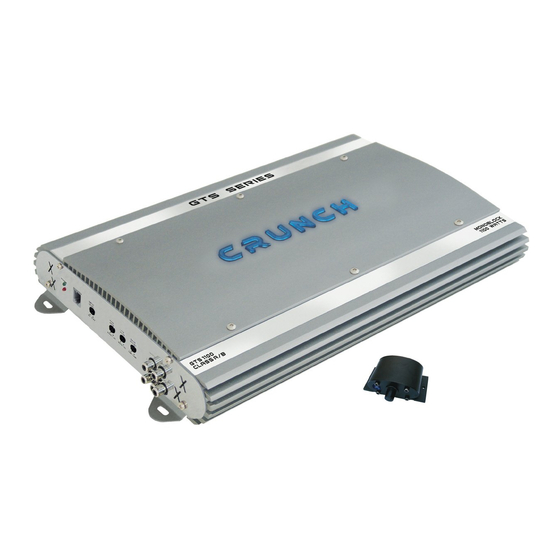
Summary of Contents for Crunch GTS1100
- Page 1 GTS1100 CLASS AB MONOBLOCK AMPLIFIER Bedienungsanleitung Owner's Manual...
-
Page 2: Technische Daten
Seite Inhaltsverzeichnis Installationshinweise, Einbau des Verstärkers, Elektrischer Anschluss GTS1100 Monoblock Funktionen und Bedienelemente Lautsprecher und Cinchanschluss Fehlerbehebung Technische Daten GTS1100 Kanäle Ausgangsleistung bei 14.4 Volt W att an 4 Ohm - RMS / MAX. 275 / 550 W att an 2 Ohm - RMS / MAX. - Page 3 Installationshinweise Achten Sie bei der Installation darauf, dass keine serienmäßig im Kfz vorhandenen Teile wie z.B. Kabel, Bordcomputer, Sicherheitsgurte, Tank oder ähnliche Teile beschädigt bzw. entfernt werden. Vergewissern Sie sich, dass der Verstärker am Montageort genügend Kühlung erhält. Montieren Sie das Gerät nicht in zu kleine, abgeschlossene Gehäuse ohne Luftzirkulation, in die Nähe von wärmeabstrahlende Teilen oder elektronische Steuerungen des Fahrzeuges.
-
Page 4: Funktionen Und Bedienelemente
Funktionen und Bedienelemente REMOTE CONTROL - Buchse SUBSONIC - Regler Zur Verbindung über Kabel mit der im Liefer- Der Subsonic-Filter erlaubt es den Subwoofer von ultratiefen umfang enthaltenen Fernbedienungs-Einheit. Frequenzen abzutrennen, damit dieser nicht mechanisch bzw. Ermöglicht die Regelung des Subwoofers elektrisch überlastet wird. -
Page 5: Lautsprecher Und Cinchanschluss
Lautsprecher und Cinchanschluss Kabelanschlüsse • Verbinden Sie die Ausgänge des Steuergerätes (Radio) mit den Cincheingängen (INPUT) des Verstärkers mittels einer • Cinchleitung. • Verbinden Sie den/die Subwoofer mittels geeigneten Kabel mit den Lautsprecher-Ausgängen (SPEAKER OUTPUT/ - +) • des Verstärkers. •... - Page 6 Fehlerbehebung Fehler: keine Funktion Ursache: 1. Die Verbindungskabel sind nicht korrekt angeschlossen. 2. Die Kabel haben keinen elektrischen und mechanischen Kontakt. 3. Sicherungen defekt. Im Falle des Austauschs achten Sie bitte auf den korrekten Wert der Sicherungen. Fehler: kein Ton aus Lautsprecher Ursache: 1.
-
Page 7: Specifications
Contents Page General Installation Notes Installation of the amplifier, Electrical Connection GTS1100 Monoblock Amplifier - Features Amplifier - Applications Trouble Shooting Specifications GTS1100 Channels Output Power Ratings at 14.4 Volts W atts at 4 Ohms - RMS / MAX. 275 / 550 W atts at 2 Ohms - RMS / MAX. -
Page 8: General Installation Notes
General Installation Notes The amplifier is generally mounted in the rear trunk area but can be mounted in any convenient area such as beneath a seat. Please be sure to locate this unit where you have reasonable air circulation and protection from moisture. When considering the mounting location you should minimize the length of the power and speaker leads. - Page 9 Amplifier - Features REMOTE CONTROL SUBSONIC The jack is for use with the enclosed remote The Subsonic filter sets the lower cut-off frequency and protects control. Only the low pass signal will be the Subwoofer from damage. The subsonic frequency is fully controlled.
- Page 10 Amplifier - Applications Interconnect cable checklist: • Connect the INPUT of the amplifier to the head unit line output with good quality RCA to RCA cables. • Connect the Subwoofer with the terminal block (SPEAKER OUTPUT/ - +) of the amplifier. •-The minimum final speaker impedance should not be lower than 1 Ohms.
-
Page 11: Trouble Shooting
Trouble Shooting System does not turn on 1. Check all fuses. 2. Check all connections. 3. Measure the +12 volt and remote turn on voltages at the amplifier terminals. If these are non existent or low, take voltage measurements at fuse holders, distribution blocks, the head unit’s +12 volt and remote leads to localize the problem. - Page 12 Distribution: Audio Design GmbH Am Breilingsweg 3 76709 Kronau / Germany Tel. 07253/9465-0, Fax 07253/9465-10 www.audiodesign.de...


Need help?
Do you have a question about the GTS1100 and is the answer not in the manual?
Questions and answers