Table of Contents
Advertisement
Advertisement
Table of Contents

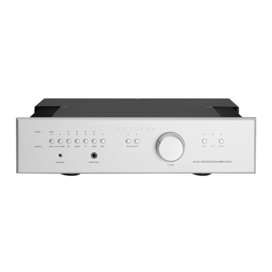
Summary of Contents for Bryston B135
- Page 1 B135 OWNER’S MANUAL...
- Page 2 Bryston authorized dealer to qualify for warranty service. The warranty is transferable from the original owner to a subsequent owner as long as a copy of the bill-of-sale from the original authorized Bryston dealer accompanies the re-sale. The copy of the bill of sale to any subsequent owner need ONLY include the Name of the Bryston Authorized Dealer and the Model and Serial number of the Bryston product The warranty will only be honored in the country of the original purchase unless otherwise pre-authorized by Bryston.
-
Page 3: Table Of Contents
• CONNECTIONS • INPUTS & OUTPUTS • LED STATUS INDICATORS..............2 • REMOTE POWER CONTROL ..............3 • PROGRAMMING THE 12V TRIGGER • HAND-HELD IR REMOTE CONTROL ............. 4 • PROGRAMMING THE IR REMOTE CONTROL • SENDING CODES to the B135 via the IR REMOTE CONTROL • WIRED RS232 REMOTE CONTROL • PASS-THROUGH MODE ................5 • DIGITAL-TO-ANALOG CONVERTER OPTION • MOVING-MAGNET PHONO STAGE OPTION • SPECIFICATIONS ..................6 • FRONT & REAR PANEL DETAILS ............7 • EXTERNAL DIMENSIONS & RECOMMENDED CLEARANCE ENVELOPE .... 8... -
Page 4: Introduction
IR sensor eye located on the front panel. If plugged in the B135 will remain in standby indicated by the RED power LED on the front panel. - Page 5 The B135 PREAMP OUT is also muted. You can adjust the volume setting of the headphones by using the volume control on the front of the B135 inte- grated amplifier. You may also utilize the remote control unit to adjust headphone volume. The headphones cannot be muted with the remote control unit or the front panel Mute.
-
Page 6: Led Status Indicators
D4 LEDs, it indicates that the digital inputs D1 (SPDIF), D2 (SPDIF), D3 (TOSLINK) or D4 (TOSLINK) have been selected. In B135 & B135-P models: when illuminated green this LED indicates that the line level ana- log audio input AUX-2 has been selected. -
Page 7: Hand-Held Ir Remote Control
WIRED RS232 REMOTE CONTROL Using the DB9-female connector at the rear of the unit, the B135 can receive commands via a null modem cable at 9600 baud, 8 data bits, no parity and 1 stop bit (9600,8,N,1). Valid commands will return the “>” character indicating that the unit is ready to receive a new command. -
Page 8: Pass-Through Mode
B135 via the IR Handheld Remote Control” & “Wired RS232 Remote Control”. To reassign PASS THROUGH mode to a different input source simply select the desired input and re-send the “245” code to the B135. To turn the deac- tivate PASS THORUGH mode, select the current Pass Through input and then send the “245” code to the B135. -
Page 9: Specifications
B135 INTEGRATED AMPLIFIER B135 SPECIFICATIONS POWER AMPLIFIER SECTION: POWER OUTPUT: Nominal: 135 watts/channel into 8Ω Maximum: 165 Watts/channel at onset of clipping into 8Ω @ 1 1/8th max: 20.6 Watts per channel into 8Ω @ 1 50K ohms single ended INPUT IMPEDANCE 1v = 100 Watts into 8 ohms (gain = 28.28 or 29dB) SENSITIVITY THD+noise: < 0.005% 20Hz to 20kHz at 135 Watts into 8 ohms, DISTORTION <... -
Page 11: External Dimensions & Recommended Clearance Envelope
B135 INTEGRATED AMPLIFIER... - Page 12 There are no user serviceable parts inside the B135. Please refer any servicing to qualified personnel. 300012-5 B135 20120329 Bryston Ltd., Peterborough, Ontario, Canada...


Need help?
Do you have a question about the B135 and is the answer not in the manual?
Questions and answers