Advertisement
INTRODUCTION
The remote control system can be operated thermostati-
cally or manually from the transmitter. The system oper-
ates on radio frequencies (RF) within a 20 foot range. Can
be used with IPI or Standing Pilot systems.
This remote control kit has a hand held transmitter that can
be used as a remote on/off or as a thermostat. The trans-
mitter display shows the current room temperature, target
temperature, timer setting, on/off status, low battery indi-
cator, current time and burner/valve operation.
If pertinent, see additional fireplace wiring diagrams on the
following pages.
INSTALLATION PRECAUTIONS
This remote control kit is tested and safe when installed in
accordance with this installation manual. Installation of this
kit MUST be done by a qualified service technician. It is the
responsibility of the installer to read all instructions before
starting installation and to follow these instructions care-
fully during installation. Modification of the remote control
system or any of its components will void the warranty and
may cause a fire hazard.
CAUTION: ALL Wiring should be done by a qualified electrician
CAUTION: All wiring should be done by a qualified electri-
and shall be in compliance with CE.
cian and shall be in compliance with local codes and with
the National Electric Code ANSI/NFPA No. 70-current (in
the United States), or with the current CSA C22.1 Canadian
Electric Code (in Canada).
WARNING:DO NO CONNECT 230 VAC WIRING TO THE
WARNING: DO NOT CONNECT 110-120 VAC WIR-
GAS CONTROL VALVE OF THIS APPLIANCE.
ING TO THE GAS CONTROL VALVE OF THIS AP-
PLIANCE.
Printed in China
Copyright 2006,
Hearth & Home Technologies Inc.
20802 Kensington Boulevard, Lakeville, MN 5504
SMART-BATT-II Remote Control Kits
- Installation and Operating Instructions -
FCC REQUIREMENTS
CE REQUIREMENTS
WARNING: CHANGES OR MODIFICATIONS TO
THIS UNIT NOT EXPRESSLY APPROVED BY THE
PARTY RESPONSIBLE FOR COMPLIANCE COULD
VOID THE USER'S AUTHORITY TO OPERATE THE
EQUIPMENT.
NOTE: This equipment has been tested and found to com-
CE. The operator is required to do as this manual says
ply with the limits for a Class B digital device, pursuant to
Part 15 of the FCC Rules. These limits are designed to
so that it will work very smart.
provide reasonable protection against harmful interference
in a residential installation. This equipment generates, uses,
and can radiate radio frequency energy and, if not installed
and used in accordance with the instructions, may cause
harmful interference to radio communications. However,
there is no guarantee that interference will not occur in a
particular installation. If this equipment does cause harmful
interference to radio or television reception, which can be
determined by turning the equipment off and on, the user is
encouraged to try to correct the interference by one or more
of the following measures:
- Reorient or relocate the receiving antenna.
- Increase the separation between the equipment and re-
ceiver.
- Connect the equipment into an outlet on a circuit differ-
ent from that to which the receiver is connected.
- Consult the dealer or an experienced radio TV techni-
cian for help.
Canadian Equipment Requirements
This digital apparatus does not exceed the (Class A/Class
B)* limits for radio noise emissions from digital apparatus
set out in the Radio Interference Regulations of the Cana-
dian Department of Communications. Le present appareil
numerique n'emet pas de bruits radioelectriques depassant
les limites applicables aux appareils numeriques (de la class
A/de la class B)* prescrites dans le Reglement sur le
brouillage radioelectrique edicte par le ministere des Com-
munications du Canada.
This device complies with RSS-210 of Industry and Sci-
ence Canada. Operation is subject to the following two con-
ditions: (1) this device may not cause interference, and (2)
this device must accept any interference, including interfer-
ence that may cause undesired operation of the device.
1
100-909G 12/06
Advertisement
Table of Contents

Related Manuals for Hearth and Home Technologies SMART-BATT-II


Summary of Contents for Hearth and Home Technologies SMART-BATT-II
- Page 1 SMART-BATT-II Remote Control Kits INTRODUCTION The remote control system can be operated thermostati- cally or manually from the transmitter. The system oper- ates on radio frequencies (RF) within a 20 foot range. Can be used with IPI or Standing Pilot systems.
-
Page 2: Hearth Mount
HEARTH MOUNT The remote receiver can be placed on the fireplace hearth (see Figure 1), or under the fireplace behind the control access panel. Position it close to the front in the right or left corner where the ambient tempera- ture inside the receiver case does not exceed 120 NOTE: The remote receiver will only respond to trans- mitter when the switch cover on the receiver is in the... - Page 3 Figure 4. Millivolt with Rocker Switch and Receiver If your fireplace is wired like Figure 3 find the leads on back of the switch marked “For use with remote or wall switch only” and take the leads and plug them into wire lead on remote receiver box (see Figure 4). B.
- Page 4 PILOT THERMOCOUPLE VALVE Figure 6. Millivolt with Receiver C. Wiring Intermittent Pilot Ignition (IPI) with Rocker Switch BLACK WIRE CAN BE PLUGGED INTO ANY OF #1 - #5 LOCATIONS ON THE HOT SIDE WHITE WIRE CAN BE PLUGGED INTO ANY OF #1-#5 LOCATIONS ON THE NEUTRAL SIDE PLUG IN...
- Page 5 If your fireplace look like Figure 7 find the leads on the back of switch marked “For use with remote or wall switch only”. Take the leads and plus them into wire leads on remote receiver box (see Figure 8). REMOTE RECEIVER WIRE...
- Page 6 D. Wiring Intermittent Pilot Ignition (IPI) with 3-Wire Assembly REM/AUX TRANS PLUG IN THERMOSTAT WIRE ASSEMBLY Figure 9. If your fireplace looks like Figure 9 remove the 3-wire off the jumper wire by unplugging the spade from jumper wire. Install the jumper wire on the wire as shown see Figure 10.
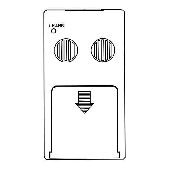
- Page 7 NOTE: The remote receiver houses the microprocessor that responds to commands from the transmitter to control sys- tem operation. It emits one beep when it receives an ON or OFF command manually, but no beep when cycling on and off automatically in THERMO mode. The remote receiver has a 3-position slide switch: OFF/RE- MOTE/ON (see Figure 11).
-
Page 8: Lcd Display Screen
1. LOW - Battery power low. Replace batteries within two weeks. 2. TIMER - Indicates time remaining before system shuts off, when timer-programmed, 9 - hour maximum setting. 3. MODE - Indicates operation MODE of system. ON indicates the system is on, either manually or thermostatically. - Page 9 ROOM 8 00 FLAME Figure 13. Setting Button/Child Proof Lockout Setting C Scale The factory setting for temperature is degrees Fahrenheit ( To change this setting to degrees Centigrade ( 1. Remove the battery cover on the back of the transmitter and locate the “setting button”...
-
Page 10: System Check
Child Proof Lockout (CP) The transmitter contains a “Child Proof” lockout feature that prevents unauthorized use of the remote control. To access the “Child Proof” activation button, remove cover on BACK of transmitter. To activate LOCKOUT: 1. Press and hold in the “setting button” for 5 seconds. The letters CP will display on the LCD screen (see Fig- ure 13). -
Page 11: General Information
4. Then press the MODE button on the transmitter to change the system to ON. The spark electrode should begin sparking to ignite the pilot. After the pilot is lit, the main gas valve should open and the main gas flame should ignite. -
Page 12: Troubleshooting
Troubleshooting To check the operation of the remote: 1. Make sure receiver batteries are installed properly. If one battery is installed backward, receiver will not operate in remote mode. Be sure battery output is 5.3 volts or more. (Slide switch is independent of battery condition). 2.
Need help?
Do you have a question about the SMART-BATT-II and is the answer not in the manual?
Questions and answers