Table of Contents
Advertisement
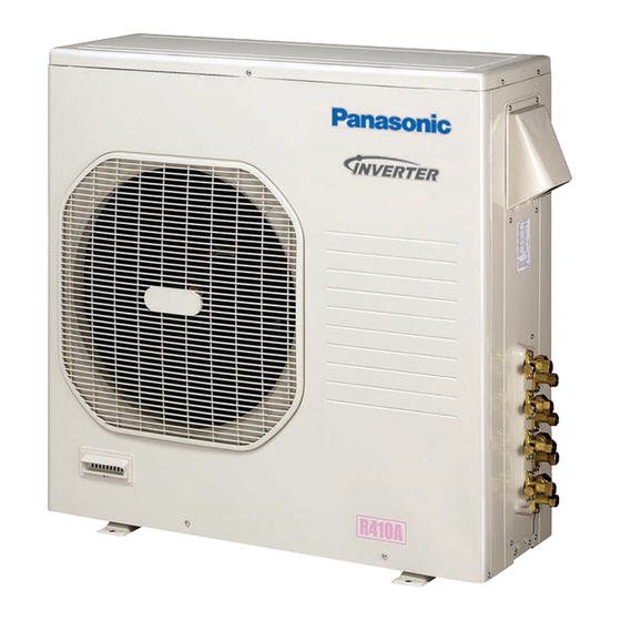
TECHNICAL & SERVICE MANUAL
OUTDOOR UNIT : CU-3KE19NBU
DC INVERTER MULTI-SYSTEM AIR CONDITIONER
CU-3KE19NBU
CU-4KE24NBU
CU-4KE31NBU
CU-4KE24NBU
CU-4KE31NBU
Capacity at 230V
Outdoor Model No.
19,100 BTU/h
CU-3KE19NBU
23,200 BTU/h
CU-4KE24NBU
30,600 BTU/h
CU-4KE31NBU
Product Code No.
1 852 361 27
1 852 361 28
1 852 361 29
< Applicable Indoor Units >
Wall mounted type
CS-MKE7NKU
CS-MKE9NKU
CS-MKE12NKU
CS-MKE18NKU
CS-MKE24NKU
Semi-concealed type
CS-MKE9NB4U & CZ-18BT1U
CS-MKE12NB4U & CZ-18BT1U
CS-KE12NB4UW & CZ-18BT1U
IMPORTANT
These air conditioners employ new
refrigerant R410A.
Pay special attention when
servicing the unit.
REFERENCE NO.
SM
700878
Advertisement
Chapters
Table of Contents


Need help?
Do you have a question about the CU-3KE19NBU and is the answer not in the manual?
Questions and answers