
Related Manuals for Digital Projection HIGHlite 12000Dsx+


Summary of Contents for Digital Projection HIGHlite 12000Dsx+
- Page 1 HIGHlite 12000Dsx+ HIGHlite 8000Dsx+ Super High Brightness Digital Video Projector User’s Manual 104-018A...
- Page 2 Declaration of Conformity Directives covered by this Declaration 89/336/EEC Electromagnetic Compatibility Directive, amended by 92/31/EEC & 93/68/EEC. 73/23/EEC Low Voltage Equipment Directive, amended by 93/68/EEC. Products covered by this Directive Large Screen Projector type HIGHlite 12000Dsx HIGHlite 8000Dsx Basis on which Conformity is being declared The products identified above comply with the protection requirements of the above EU directives, and the manufacturer has applied the following standards:- EN55022:1998 - Limits and Methods of Measurements of Radio Disturbance Characteristics of...
-
Page 3: Important Information
Important Information CAUTION: To turn off the main power, be sure to remove the Precautions: Please read this manual carefully before us- plug from power outlet. The power outlet socket should be ing your HIGHlite 12000Dsx+ HIGHlite 8000Dsx+ Projector installed as near to the equipment as possible, and should be and keep the manual handy for future reference. -
Page 4: Important Safeguards
Important Information Fire and Shock Precautions Important Safeguards These safety instructions are to ensure the long life of your pro- 1. Ensure that there is sufficient ventilation and that vents are unobstructed to prevent potentially dangerous concentrations of ozone and the build- jector and to prevent fire and shock. - Page 5 Important Information Recommandations importantes projecteur. Laisser au moins 20 cm d’espace entre le projecteur et un mur. Veuillez laisser un espace libre d’au moins 50 cm (20 pouces) Ces instructions de sécurité ont pour but d’assurer une longue entre les orifices de ventilation et l’objet. vie à...
-
Page 6: Wichtige Sicherheitshinweise
Important Information Achtung: Um die Netzspannung komplett abzuschalten, Wichtige Sicherheitshinweise stellen Sie sicher, daß der Netzstecker aus der Netzsteckdose Diese Sicherheitshinweise sollen eine lange Lebensdauer Ihres gezogen wurde. Die Netzsteckdose sollte so nahe als möglich Projektors sicherstellen und vor Feuer und elektrischen Schlägen vom Gerät entfernt und leicht zugänglich sein. - Page 7 Important Information Vorsichtsmaßnahmen zur Vermeidung von Bränden und VORSICHT elektrischen Schlägen Unter den nachfolgend aufgeführten Umständen darf das 1. Sorgen Sie für ausreichende Belüftung und stellen Sie außerdem sicher, Netzkabel nicht von der Netzsteckdose abgetrennt werden, dass die Lüftungsschlitze frei bleiben, damit sich innerhalb des da dies Beschädigungen des Projektors verursachen könnte: Projektors kein Hitzestau bilden kann.
-
Page 8: Table Of Contents
Table of Contents 1. Introduction ..........E-9 Ref. Adjust ................E-55 1 What's in the Box? ..............E-10 3D Reform ................. E-55 2 Features .................. E-11 Screen ................E-56 3 Getting to Know Your Projector ..........E-12 Ref. Lens Memory ............. E-56 Edge Blending .............. - Page 9 Introduction 1 What's in the Box? ..........E-10 2 Features ..............E-11 3 Getting to Know Your Projector ......E-12 Control Panel ....................E-13 Control Terminals ..................... E-14 Input Terminals ....................E-15 Option Boards ....................E-16 4 Remote Control Features ........E-17 Remote Control Precautions ................
-
Page 10: Introduction
1. Introduction 1 What's in the Box? Make sure your box contains everything listed. If any pieces are missing, contact your dealer. Please save the original box and packing materials if you ever need to ship your Projector. HIGHlite 12000Dsx+ Projector (USA model 103-487, ROW model 103-488) HIGHlite 8000Dsx+ Projector (USA model 103-757, ROW model 103-758) -
Page 11: Features
1. Introduction 2 Features • DigiWarp - Geometric Warp Correction Function In the case pictures are projected on particular shaped screens • HDTV support, suited to 3D movement and telecine, with (cylindrical or spherical), geometric warp can be corrected by I/P conversion implementing MM-WARP (optional). -
Page 12: Getting To Know Your Projector
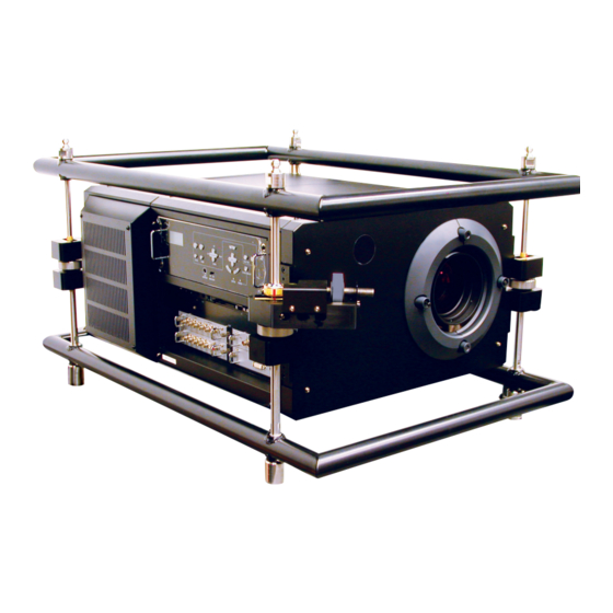
1. Introduction 3 Getting to Know Your Projector Frame Control panel (See page E-13) Tilt Adjustment Knob Remote sensor Lens (optional) Control terminals (See page E-14) Input terminals (See page E-15) Roll Adjustment Knob PAN Adjustment Knob NOTE: The frame is not included on HIGHlite 8000Dsx+. Remote sensor Main power switch (See page E-30) - Page 13 1. Introduction Control Panel 13 12 1. LCD Screen 9. SHUTTER Button The liquid crystal display screen shows the condition or the While pressing and holding CTL Button, pressing this button error message of the Projector. shuts off the light completely. 2.
-
Page 14: Control Terminals
1. Introduction Control Terminals 1. USB Port (USB B)(Type B) 6. PC CARD Slot Connect this port to the USB port (type A) of your PC using a Insert a PC card, commercially available flash memory card or USB cable. optional wireless LAN card here. -
Page 15: Input Terminals
1. Introduction Input Terminals 1. SLOT 1 (MM-VIDEO) 2. SLOT 2 (MM-RGB) MM-VIDEO interface board is standard equipment. MM-RGB interface board is standard equipment. (1) CVBS Input Connector (BNC Type) (1) RGB Input Connectors (5 BNC Type) Use a 75 Ω coaxial cable and connect it to the Composite Use a 75 Ω... -
Page 16: Option Boards
1. Introduction Option Boards MM-DVI Interface Board (Option) MM-SDI Interface Board (Option) The DVI digital signal input board is available as an option. The SDI signal input board is available as an option. (1) DVI-D Input Connector (DVI-D 24 Pin) (1) STATUS Indicator Use a DVI-D Signal cable and connect it to the DVI output Steady green light ... -
Page 17: Remote Control Features
1. Introduction 4 Remote Control Features 1. POWER ON Press and hold this button for a minimum of 1 second to turn on the Projector when the main power is supplied and the Pro- jector is in standby mode. 2. POWER OFF Press and hold this button for a minimum of 1 second to turn POWER INPUT... - Page 18 1. Introduction 11. ENTRY LIST 22. ENTER Press to display the Entry List screen. Executes the menu selection and activates items selected from Pressing and holding CTL and then ENTRY LIST buttons si- the menu. When the slider or dialog box is displayed: multaneously, enters a signal in the Entry List.
-
Page 19: Remote Control Precautions
1. Introduction Remote Control Precautions Operating Range for Wireless Remote Control • The remote control system may not function when direct sunlight or The infrared signal operates by line-of-sight up to a distance of strong illumination strikes the remote control sensor of the main unit, or approximately 7m (20 feet) and a 60 degree angle of the remote when there is an obstacle in the path. -
Page 20: Using The Remote Control In Wired Operation
1. Introduction Using the Remote Control in Wired Operation Connect one end of the supplied remote cable to the REMOTE IN 1 mini jack and the other end to the remote jack on the remote control. NOTE: Do not use this jack for anything other than intended use. REMOTE IN 1 Remote cable (supplied) - Page 21 Installation 1 Setting Up Your Projector ........E-21 Screen Size and Projection Distance ............... E-22 Table of Throw Distances and Image Sizes for Optional Lenses ..... E-22 2 Lens Shift Adjustable Range ......... E-23 Maximum Possible Range for SL-14Z / SL-18Z / SL-25Z / SL-45Z ....E-23 3 Making Connections ..........
-
Page 22: Installation
2. Installation This section describes how to set up your projector and how to Screen Size and Projection Distance connect video and audio sources. Applicable lens and throw distance/ List of screen sizes 1 Setting Up Your Projector Your Projector is simple to set up and use. But before you get started, you must first: 1. -
Page 23: Lens Shift Adjustable Range
2. Installation 2 Lens Shift Adjustable Range Lens Shift Adjustable Range for Desktop and Ceiling Mount Application The diagram below shows the location of the image position in the lens. The lens can be shifted within the shaded area as shown using the normal projection position as a starting point. Maximum Possible Range for SL-14Z / SL-18Z / SL-25Z / SL-45Z Parenthesized values for the ceiling mount application Up: 0.45 V (0.14 V) -
Page 24: Making Connections
2. Installation 3 Making Connections Connecting to the Image Input Terminals This Projector has two interface boards, MM-VIDEO and MM-RGB as standard equipment. See page E-11. Connect required video signals. Four interface boards can be inserted in the Projector at the same time. See Page E-25. COMPONENT HIGHlite 12000Dsx+ RCA(female)-to-BNC(male) - Page 25 2. Installation 4. Tighten the 2 screws located at right and left of the board and fasten Installing Additional Option Boards securely. Four types of option boards are available for the Projector. Please purchase as required. Warning Ensure main power is disconnected or by turning off the main power switch before installing or re- moving the board from the Projector.
-
Page 26: Connecting To A Network
2. Installation Connecting to a Network With the LAN connection, you can control the Projector over the network using a computer to turn the Projector on/off, select the input and others. Server Example of LAN connection Ethernet cable (not supplied) HIGHlite 12000Dsx+ Using the HTTP Server function 2. - Page 27 2. Installation Connnecting the Power Cable After making certain that the main power switch of your projector is OFF, connect the power cable to a 200 to 240 VAC three-prong outlet (grounded). Two versions of the projector are available: USA models are supplied with a Hubbel type connector, for Rest of World a CEE-Form connector is supplied.
-
Page 28: Inserting And Removing A Pc Card
2. Installation Inserting and Removing a PC Card PC Card Type The PC Card slot accepts PCMCIA Type II only. NOTE: • Do not try to force the PC card into the slot. NOTE: The projector does not support FAT32 or NTFS formatted flash memory card or USB memory device. - Page 29 Projecting an Image (Basic Operation) 1 Turning on the Projector ........E-30 2 Selecting a Source ..........E-31 3 Adjusting the Picture Size and Position ....E-31 4 Optimizing RGB Picture Automatically ....E-33 5 Turning off the Projector ........E-33 E-29...
-
Page 30: Projecting An Image (Basic Operation
3. Projecting an Image This chapter describes how to turn on the Projector and to project a picture onto the screen. 1 Turning on the Projector NOTE: • When plugging in or unplugging the supplied power cable, make sure that the main power switch is pushed to the off[O] position. -
Page 31: Selecting A Source
3. Projecting an Image 2 Selecting a Source 3 Adjusting the Picture Size and Position Selecting the computer or video source 1. Turn on the projector 2. Select your type of projector orientation. Using the Remote Control Desktop front, ceiling rear, desktop rear, and ceiling front. POWER INPUT Press the Source/Input button... - Page 32 3. Projecting an Image (2) Press and hold the CTL and press the ZOOM + or - button to adjust the image size. You can also adjust the image size by using the CTR button and the ZOOM + or - button on the projector cabinet. CANCEL FOCUS MAGNIFY/...
-
Page 33: Optimizing Rgb Picture Automatically
3. Projecting an Image 4 Optimizing RGB Picture Automatically 5 Turning off the Projector Adjusting the Image Using Auto Adjust To turn off the Projector: Optimizing RGB image automatically First press the POWER (ON/STAND BY) button on the Projector cabinet or the POWER OFF button on the remote control for a 1. - Page 34 E-34...
-
Page 35: Convenient Features
Convenient Features 1 Turning Off the Image ..........E-36 2 Getting the On-line Help and Information ....E-36 3 Lens Memory ............E-36 E-35... -
Page 36: Turning Off The Image
4. Convenient Features 1 Turning Off the Image 3 Lens Memory Press the MUTE PICTURE button to turn off the image for a short period of time. Press again to restore the image. Press the MUTE OSD button to turn off the on-screen display. Press again to restore the on-screen display. -
Page 37: Setting Up For Ouble Stacking
Setting Up for Double Stacking 1 Stacking and Connecting the Projectors ....E-38 2 Adjusting and Registering Signals to Be Projected ..E-41 3 Adjusting the Lens Shift, Zoom and Focus to Clearly Display all projected patterns ....E-41 E-37... -
Page 38: Stacking And Connecting The Projectors
5. Setting Up for Double Stacking in Link Mode 1 Stacking and Connecting the Projectors NOTE: Up to two units can be gravity stacked without external support. In some cases, however, two images will not align on the screen correctly. This will become more apparent when displaying small text and detailed graphics. - Page 39 5. Setting Up for Double Stacking in Link Mode Connect projectors using Ball-lock Pins. Place projectors together. 4. Insert all four Ball-lock Pins back into Master Projector stacking connectors Master Projector Join using stacking 3. Stack projectors connectors Slave Projector Slave Projector 1-2.
-
Page 40: Setting Up For Double Stacking In Link Mode
5. Setting Up for Double Stacking in Link Mode 13-1. Select “Projector Options” → “Setup” → “Page4” → “Pro- 1-3-3. On the remote control specify the ID number of the pro- jector to be adjusted. Press and hold the CTL and press jector ID”... - Page 41 5. Setting Up for Double Stacking in Link Mode 1-6. Control Cable Connection Example of Remote Controllers Control Remote controller and master projector’s remote controller input 1 port (REMOTE1 IN 1 )are connected by remote cable. Master projector’s remote output port (REMOTE OUT) and slave projector’s remote controller input 1 port (REMOTE IN 1) are connected by remote cable.
-
Page 42: Adjusting And Registering Signals To Be Projected
5. Setting Up for Double Stacking in Link Mode 2 Adjusting and Registering Signals to Be Projected 2-1. Making Adjustments to the Master Projector 2-1-1. Display a desired input signal on the master projector. 2-1-2. Make adjustment to the signal, then save (register) ad- justments on the master projector by pressing and holding CTL and pressing ENTRY LIST button on the remote con- trol. - Page 43 Using On-Screen Menu 1 Basic Menu Operation ......E-44 Edge Blending ........E-57 2 List of Direct Button Combinations ..E-45 Lamp Mode ........E-58 3 Using the USB Mouse ......E-45 Factory Default ........E-58 4 Menu Tree ..........E-46 Projector Options ........
-
Page 44: Using On-Screen Menu
6. Using On-Screen Menu 1 Basic Menu Operation Customizing the Menu The Custom menu can be customized to meet your requirements. Using the Menus Selecting a menu item from the "Custom Menu Edit" list, allows you to custom tailor the menu items to your needs. 1. -
Page 45: List Of Direct Button Combinations
6. Using On-Screen Menu 2 List of Direct Button Combinations CTL+ Input (1-10) Switches to any selected signal found in the Entry List. To enable this combination, you must first assign specific remote buttons for direct input selection in the Entry Edit window. CTL+ ENTER (While displaying Entry list) Displays the selected signal. -
Page 46: Menu Tree
6. Using On-Screen Menu 4 Menu Tree NOTE: The shaded item indicates the default setting. S1: Video Advanced Menu S1: S-Video Source Select S1: Component * When the interface boards are installed at the factory. Adjust (Source) S2: RGB S3: None Ref. -
Page 47: Source Select
6. Using On-Screen Menu NOTE: The shaded item indicates the default setting. 3D Reform Cornerstone 8 direction / close Advanced Menu decrease ←→ increase Keystone Source Select (When MM-WARP (optional) is inserted, horizontal / vertical) Adjust (Source) Screen Screen Type 1.25:1(5:4) / 1.33:1(4:3) / 1.78:1(16:9) / 1.85:1 / 2.35:1 Position -64 to 64... - Page 48 6. Using On-Screen Menu NOTE: The shaded item indicates the default setting. LAN Mode Status LAN Card Build-in / PC Card Advanced Menu Projector Name Source Select IP Address Subnet Mask Adjust (Source) Gateway Ref. Adjust MAC Address Advanced IP Address Automatic / Manual Factory Default IP Address...
- Page 49 6. Using On-Screen Menu Contents Advanced Menu Source Information Page 1 Source Name / Input Terminal / Entry No. / Source Select Horizontal Frequency / Vertical Frequency / Sync Polarity Page 2 Signal Type / Video Type / Sync Type / Interlace / Direct Key Adjust (Source) Projector Information Page 1 Serial Number / Remaining Lamp Time / Lamp Hour Meter /...
- Page 50 6. Using On-Screen Menu 5 Menu Descriptions & Functions Entering Alphanumeric Characters by Using the Menu Alphabet or numeric characters are used for your IP address or Projector name. To enter IP Address or Projector name, use the Source Select software keyboard.
-
Page 51: Adjust (Source
6. Using On-Screen Menu Store .... Enables you to store the currently projected sig- Colour nal. Increases or decreases the colour saturation level (not avail- able for RGB). NOTE: This can be done by pressing CTL and ENTRY LIST buttons. Cut .... -
Page 52: Colour Management
6. Using On-Screen Menu DigiView - SweetVision Setup relating to picture colour will be done. Vivid palette, pastel vision, colour temprature and white balance can be adjusted as your choice. Each set value is saved as exclusive use of projected signal set value, and also those can be saved as default value for this equip- ment. -
Page 53: Image Options
6. Using On-Screen Menu PAL/SECAM Enhanced ..Correction fit to PAL signals and Synchronize SECAM signals are done. Gamma 1.0 - 3.0 ....Gamma value is set by 0.1 step. Image Options Pixel Adjust Displays the Clock and Phase adjustments. Sets display vertical frequency to be synchronized with input sig- nal. -
Page 54: Option Adjust
6. Using On-Screen Menu Input Position NOTE: When connecting with a scan converter: If an image from the scan converter is not correctly displayed, adjust to select the best level point so that the image is displayed correctly. Field Invert: (Upgrade support scheduled) This feature is used to correct diagonal lines of a non-standard interlaced signal when they appear jaggy. -
Page 55: Signal Type
6. Using On-Screen Menu Signal Type Keystone Correction Select either the RGB signal type or the Component signal type. RGB .... RGB signal Component .. Component signals such as Y/Cb/Cr, Y/Pb/Pr NOTE: This feature is available on RGB only. If you do not get a better picture even when you set "Signal Select"... -
Page 56: Ref. Lens Memory
(cylindical or spherical) can be ad- justed by an application software, Geometric Correction Tool. The Geometric Correction Tool is available from Digital Projection please contact Screen your dealer. Geometric Correction Tool version 2.0.3 or higher is recommended. -
Page 57: Edge Blending
6. Using On-Screen Menu 1. Using the test pattern “Cross Hatch” of the Projector, superimpose the NOTE: This option is only available when screens so that the height of the 2 projected screens is the same and "Yes" is selected for "Use Point on Signal the distortion disappears. -
Page 58: Lamp Mode
6. Using On-Screen Menu Lamp Mode Projector Options Menu [Page 1] Lamp brightness can be adjusted to 8 levels or automatically adjusted. Adjust ..Choices of levels: 65%, 70%, 80%, 85%, 90%, 95%, 100% Auto ..... Automatic adjustment is made when “ON” is se- lected. -
Page 59: Setup
The default background is "Blue". NOTE: The Message selections are: • When “Logo” is selected, the “DIGITAL PROJECTION” logo is displayed. “Wait a moment”. • The background will not change when the Factory Default is performed. - Page 60 6. Using On-Screen Menu [Page 2] [Page 3] Selecting Signal Format [Signal Select] Enabling Auto Adjust [Auto Adjust] When "Auto Adjust" is set to "On", the Projector automatically Allows you to choose "RGB" for an RGB source such as a determines the best resolution for the current RGB input sig- computer, or "Component"...
- Page 61 6. Using On-Screen Menu Lens Shutter on During Signal Switching [Page 4] While switching the signals (screen image is muted), the light can be absolutely shut out from the lens simultaneously with shutter. With Check Mark ....While switching the signals and muting the images, shutter is simultaneously activated.
-
Page 62: Lan Mode
6. Using On-Screen Menu Auto ..... Searches for an active source in order of Slot 1 Projector Name → Slot 2 → Slot 3 → Slot 4 → Slot 1 and dis- Specify a unique Projector name. Press H to display the soft- plays the first found source. - Page 63 6. Using On-Screen Menu Gateway ..Set the default gateway of the network connected SSID (Network name): to the Projector. Press H to display the software Enter an identifier (SSID) for wireless LAN. Communication keyboard and type in 12 numeric characters. can be done only with equipment whose SSID matches SSID for your wireless LAN.
- Page 64 6. Using On-Screen Menu Key1-4: Mail Enter encryption key when selecting [64bit] or [128bit] in [WEP]. Up to 5 characters can be set in 64 bit and up to 13 characters in 128 bit. Press the “HEX” button to change to “ASCII” to set the key in ASCII digit.
-
Page 65: Image Mode
6. Using On-Screen Menu Image Mode Entry To assign your password: NOTE: • Up to 15 alphanumeric characters can be assigned. • Only numbers can be entered when you use the remote control Source/Input buttons. 1. Type a password. Installation of the MM-IMGPRO and MM-SCALING options per- Highlight “Entry”... -
Page 66: Security
6. Using On-Screen Menu 1. Use the SELECT GH button to select “Keyword” and use the software 4. Use the Software keyboard to type “5555”. Highlight “OK” on the “Password” entry screen and then press the EN- keyboard to enter a keyword. TER button. -
Page 67: Tools
PC card. * Formatting your registered PC card will disable your protect key function. NOTE: For additional information contact your dealer or Digital Projection 2. Select a program number (No. 1 to 10) by using the SELECT G or H button. - Page 68 6. Using On-Screen Menu 3. Select “Edit” and press the ENTER button to open the Edit window. Enabling the On or Off Timer 1. To execute the setting, select “Active” . 4. Set the Day, Time (24 hours format), On-Time and Off-Time using the SELECT buttons and the Software keyboard (1 thru 10).
-
Page 69: Pc Card Files
6. Using On-Screen Menu Enabling Sleep Timer Help Contents 1. Select your desired time between 30 minutes and 16 hours: Off, 0:30, 1:00, 2:00, 4:00, 8:00, 12:00, 16:00. 2. Select “Set” and press the ENTER button on the remote control. 3. -
Page 70: Projector Information
6. Using On-Screen Menu Page 2 Page 3 Version (Formatter Red) (Boot App / Config / Degamma / Main App / Sequences) Signal Type, Video Type, Sync Type, Interlace, Direct Key Page 4 Projector Information Displays the information for your Projector such as Remaining Lamp Time, Lamp Hour Meter, Projector Usage, Projector ID, version number and others. -
Page 71: Test Pattern
6. Using On-Screen Menu Test Pattern Press to display the test pattern. Pressing this button sequen- tially selects 17 test patterns for each red, green and blue. E-71... - Page 72 E-72...
-
Page 73: Maintenance
Maintenance 1 Cleaning the Cabinet and the Lens ......E-74 E-73... -
Page 74: Cleaning The Cabinet And The Lens
7. Maintenance 1 Cleaning the Cabinet and the Lens 1. Turn off the Projector before cleaning. 2. Clean the cabinet periodically with a damp cloth. If heavily soiled, use a mild detergent. Never use strong detergents or solvents such as alcohol or thinner. - Page 75 Appendix 1 Troubleshooting ............E-76 2 Specifications ............E-78 3 Cabinet Dimensions ..........E-80 4 Compatible Input Signal List ........E-82 5 Pin Assignment of PC CONTROL IN Connector (D-Sub 9 Pin) ..E-83 6 Pin Assignment of REMOTE IN 3 Connector (XLR connector) ..E-83 7 Pin Assignment of EXT.
-
Page 76: Appendix
8. Appendix 1 Troubleshooting This section helps you resolve problems you may encounter while setting up or using the projector. Power Indicator Indicator Condition Projector Condition Note The main power is off – Blinking light Green blinking 0.5 sec ON, The projector is getting ready to turn on. - Page 77 8. Appendix Common Problems & Solutions Problem Check These Items Does not turn on • Check that the power cable is plugged in and that the main power switch on the projector is on. See pages E- 27 and E-30. •...
-
Page 78: Specifications
8. Appendix 2 Specifications Model Number HIGHlite 12000Dsx+ / HIGHlite 8000Dsx+ Panel 0.95” 3 Output Resolution 1400 1050 native resolution Compatible with input resolution up to 1600 1200 with DigiScale Lamp 2.0kW Bulb Type Short Arc Xenon Built in: Overheat Protection Lamp Over-Usage Protection Light Output 11,000 Lumens (HIGHlite 12000Dsx+) - Page 79 8. Appendix MM-SDI SDTV : SMPTE 259M Level-C (Optional Board) HDTV : SMPTE 292M (include 24sF,24p) (includes 1080i/60, 1080i50, 24sF, 25p, 24p 23.98p/sF, 720p/60 but not 60p) Input / Output Terminal Input Slot 4 slots (One board each for the VIDEO board and analog RGB input board are standard equipment; 2 slots are for expansion.) MM-VIDEO Video...
-
Page 80: Cabinet Dimensions
8. Appendix 3 Cabinet Dimensions HIGHlite 12000Dsx+ 532(20.9) 668(26.3) 80(3.2) 42(1.7) 410(16.1 ) 690(27.2) 636(25.1) 108(4.3) Lens Center 486(19.2) Unit = mm (inch) E-80... - Page 81 8. Appendix HIGHlite 8000Dsx+ 425(16.7) 400(15.8) 670(26.4) (4.3) Lens Center Unit = mm (inch) E-81...
-
Page 82: Compatible Input Signal List
8. Appendix 4 Compatible Input Signal List Signal Resolution Frequency H. Refresh Rate MM-RGB ( Dots ) ( kHz ) ( Hz ) VIDEO RGsB RGBS RGBHV YCrCb SDI VIDEO NTSC – 15.7 60.0 (Composite PAL/SECAM – 15.6 50.0 S-Video) PAL60 –... -
Page 83: Pin Assignment Of Pc Control In Connector (D-Sub 9 Pin
8. Appendix 5 Pin Assignment of PC CONTROL IN Con- 7 Pin Assignment of EXT. I/O Connector nector (D-Sub 9 Pin) (Mini D-Sub 15 Pin) The various control and switching operations are enabled by ei- ther opening (OPEN) or short circuiting (SHORT) the pin number 15 (GND) of the external control connector (EXT. -
Page 84: Using Software Keyboard
8. Appendix 8 Using Software Keyboard 9 Operation Using an HTTP Browser Overview The use of HTTP server functions will allow control of the Projec- tor from a web browser without the installation of special soft- ware. Please be sure to use “Microsoft Internet Explorer 4.x” or a higher version for the web browser. - Page 85 8. Appendix Structure of the HTTP Server Picture: Controls the video adjustment of the Projector. Brightness G Increments the brightness adjustment value. Brightness H Decrements the brightness adjustment value. Contrast G ... Increments the contrast adjustment value. Contrast H ... Decrements the contrast adjustment value. Saturation G Increments the saturation adjustment value.
-
Page 86: Index
INDEX NUMBER 3D Reform ................E-55 Factory Default ..............E-58 3D Sequence Set Select ............ E-61 Ferrite clamp core ............. E-10,E-24 3D Y/C Separation ............. E-52 Frame ................. E-12 Adjust (Source) ..............E-51 Gamma Correction ............. E-52 Advanced ................E-62 Gateway ................ - Page 87 INDEX On / Off Timer ..............E-67 Telecine ................E-52 Option Adjust ..............E-54 Test Mail ................E-64 Option Boards ..............E-16 Test Pattern ................ E-71 Orientation ................. E-59 Timer .................. E-67 Overscan ................E-53 Tools ................... E-67 TX rate ................E-63 Password ................
- Page 88 E-88...
- Page 89 E-89...
- Page 90 E-90...
Need help?
Do you have a question about the HIGHlite 12000Dsx+ and is the answer not in the manual?
Questions and answers