Table of Contents
Advertisement
www.proform.com
USER'S MANUAL
Model No. PFTL39511.0
Serial No.
Write the serial number in the space
above for reference.
Serial Number
Decal
QUESTIONS?
If you have questions, or if parts
are damaged or missing, DO NOT
CONTACT THE STORE; please
contact Customer Care.
IMPORTANT: Please register this
product (see the limited warranty
on the back cover of this manual)
before contacting Customer Care.
CALL TOLL-FREE:
1-888-533-1333
Mon.–Fri., 6 a.m.–6 p.m. MT
Sat. 8 a.m.–4 p.m. MT
ON THE WEB:
www.proformservice.com
CAUTION
Read all precautions and instruc-
tions in this manual before using
this equipment. Keep this manual
for future reference.
Advertisement
Table of Contents

Subscribe to Our Youtube Channel
Related Manuals for Pro-Form PFTL39511.0


Summary of Contents for Pro-Form PFTL39511.0
- Page 1 USER’S MANUAL Model No. PFTL39511.0 Serial No. Write the serial number in the space above for reference. Serial Number Decal QUESTIONS? If you have questions, or if parts are damaged or missing, DO NOT CONTACT THE STORE; please contact Customer Care.
-
Page 2: Table Of Contents
Apply the decal in the location shown. Note: The decals may not be shown at actual size. PROFORM is a registered trademark of ICON IP, Inc. -
Page 3: Important Precautions
To reduce the risk of serious injury, read all important precations and in- structions in this manual and all warnings on your treadmill before using your treadmill. ICON as- sumes no responsibility for personal injury or property damage sustained by or through the use of this product. - Page 4 20. Never leave the treadmill unattended while 24. Inspect and properly tighten all parts of the it is running. Always remove the key, unplug treadmill regularly. the power cord, and press the power switch DANGER: Always unplug the power into the off position when the treadmill is not cord immediately after use, before clean- in use.
-
Page 5: Before You Begin
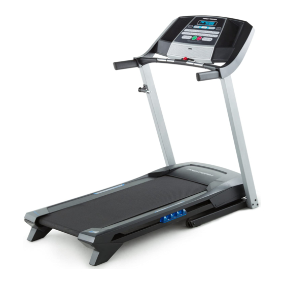
BEFORE YOU BEGIN Thank you for selecting the new PROFORM 6.0 RT manual. To help us assist you, note the product model ® treadmill. The 6.0 RT treadmill provides an impressive number and serial number before contacting us. The selection of features designed to make your workouts model number and the location of the serial number at home more effective and enjoyable. -
Page 6: Part Identification Chart
PART IDENTIFICATION CHART Use the drawings below to identify small parts used for assembly. The number in parentheses below each draw- ing is the key number of the part, from the PART LIST near the end of this manual. The number following the key number is the quantity used for assembly. -
Page 7: Assembly
ASSEMBLY • To hire a service technician to assemble this prod- is lubricant on top of the walking belt, wipe it off uct in your home, call 1-800-445-2480. with a soft cloth and a mild, non-abrasive cleaner. • Assembly requires two persons. • To identify small parts, see page 6. - Page 8 3. Identify the Right Upright (76), which is marked “Right.” Have a second person hold the Right Upright near the Base (74). See the inset drawing. Tie the wire tie in the Right Upright (76) securely around the end of the Upright Wire (63).
- Page 9 5. Identify the Right Handrail (64), which is marked “Right.” Have a second person hold the Right Handrail near the Right Upright (76). Route the Upright Wire (63) into the bottom of the Right Handrail (64) and out of the hole in the Right Handrail.
- Page 10 7. Remove the four screws (D) from the Left and Right Handrails (59, 64). Discard the screws. 8. Attach the Console Crossbar (61) to the Left and Right Uprights (66, 76) with four #10 x 3/4" Screws (8) and four #10 Star Washers (23). Start all four Screws, and then tighten them.
- Page 11 9. With the help of a second person, hold the con- sole assembly near the Right Handrail (64). Connect the Upright Wire (63) to the console Console wire. See the inset drawing. The connectors Assembly should slide together easily and snap into place.
- Page 12 11. Attach the Latch Housing (67) to the Left Upright (66) with two #10 x 3/4" Screws (8); start both Screws, and then tighten them. Make sure that the large hole in the Latch Housing is on the indicated side. Locate the Latch Pin Assembly (68).
-
Page 13: Operation And Adjustment
OPERATION AND ADJUSTMENT HOW TO PLUG IN THE POWER CORD This product is for use on a nominal 120-volt circuit (see drawing 1). A temporary adapter may be used to connect the surge suppressor to a 2-pole receptacle if DANGER: a properly-grounded outlet is not available (see Improper connec- drawing 2). - Page 14 CONSOLE DIAGRAM FEATURES OF THE CONSOLE IMPORTANT: If there is a sheet of plastic on the face of the console, remove the plastic. To prevent The treadmill console offers a selection of features damage to the walking platform, wear clean ath- designed to make your workouts more effective.
-
Page 15: To Use Manual Mode
HOW TO TURN ON THE POWER HOW TO USE THE MANUAL MODE IMPORTANT: If the treadmill has been exposed to 1. Insert the key into the console. cold temperatures, allow it to warm to room tem- perature before turning on the power. If you do not See HOW TO TURN ON THE POWER at the left. - Page 16 4. Change the incline of the treadmill as desired. burned, or the speed of the walking belt. Press the Priority Display button repeatedly until the upper To change the incline of the treadmill, press the display shows the information that you are most Incline increase and decrease buttons or one of interested in viewing.
-
Page 17: To Use A Preset Workout
HOW TO USE A PRESET WORKOUT programmed for the next segment, the speed and/ or incline setting will flash in the display to alert 1. Insert the key into the console. you. The treadmill will then automatically adjust to the speed and incline settings for the next segment. See HOW TO TURN ON THE POWER on page 15. The workout will continue in this way until the last 2. - Page 18 THE INFORMATION MODE An “E” for English miles or an “M” for metric kilometers will appear in the lower right display. Press the Speed The console features an information mode that keeps increase button to change the unit of measurement, if track of treadmill usage information and allows you to desired.
-
Page 19: How To Fold And Move The Treadmill
HOW TO FOLD AND MOVE THE TREADMILL HOW TO FOLD THE TREADMILL HOW TO MOVE THE TREADMILL Before folding the treadmill, adjust the incline to Before moving the treadmill, fold it as described at the the lowest position. If you do not do this, you may left. -
Page 20: Troubleshooting
TROUBLESHOOTING Most treadmill problems can be solved by following c. Remove the key from the console, and then the simple steps below. Find the symptom that reinsert it. applies, and follow the steps listed. If further assis- tance is needed, see the front cover of this manual. d. - Page 21 Locate the Reed Switch (33) and the Magnet (32) b. If the walking belt is overtightened, treadmill per- on the right side of the Pulley (31). Turn the Pulley formance may decrease and the walking belt may until the Magnet is aligned with the Reed Switch. become damaged.
- Page 22 SYMPTOM: The walking belt is off-center or slips b. If the walking belt slips when walked on, first re- when walked on move the key and UNPLUG THE POWER CORD. Using the hex key, turn both idler roller screws a. If the walking belt is off-center, first remove the clockwise, 1/4 of a turn.
-
Page 23: Exercise Guidelines
EXERCISE GUIDELINES Burning Fat—To burn fat effectively, you must exer- WARNING: cise at a low intensity level for a sustained period of Before beginning this time. During the first few minutes of exercise, your or any exercise program, consult your physi- body uses carbohydrate calories for energy. -
Page 24: Part List
PART LIST Model No. PFTL39511.0 R0911A Key No. Qty. Description Key No. Qty. Description #8 x 1/2" Ground Screw Left Rear Foot 3/8" x 3 1/4" Screw Hex Key 3/8" Star Washer 5/32" Hex Key #8 x 3/4" Screw Right Rear Foot 5/16"... -
Page 25: Exploded Drawing
EXPLODED DRAWING A Model No. PFTL39511.0 R0911A... - Page 26 EXPLODED DRAWING B Model No. PFTL39511.0 R0911A...
- Page 27 EXPLODED DRAWING C Model No. PFTL39511.0 R0911A 10 75...
-
Page 28: Ordering Replacement Parts
ICON’s option, the product through one of its authorized service centers. All repairs for which warranty claims are made must be preauthorized by ICON. If the product is shipped to a service center, freight charges to and from the service center will be the customer’s responsibility. If replacement parts are shipped while the product is under warranty, the customer will be responsible for a minimal handling charge.
Need help?
Do you have a question about the PFTL39511.0 and is the answer not in the manual?
Questions and answers