Table of Contents
Troubleshooting

Related Manuals for Panasonic KX-TG8011MES


Summary of Contents for Panasonic KX-TG8011MES
- Page 1 ORDER NO. KM40811756CE Telephone Equipment KX-TG8011MES Model No. KX-TGA800MES Digital Cordless Phone S:Silver Version (for Mexico) © Panasonic Communications Co., Ltd 2008. Unau- thorized copying and distribution is a violation of law.
- Page 2 KX-TG8011MES/KX-TGA800MES...
-
Page 3: Table Of Contents
KX-TG8011MES/KX-TGA800MES TABLE OF CONTENTS PAGE PAGE 1 Safety Precautions----------------------------------------------- 4 15 Exploded View and Replacement Parts List ----------- 79 1.1. For Service Technicians --------------------------------- 4 15.1. Cabinet and Electrical Parts (Base Unit) ----------- 79 2 Warning -------------------------------------------------------------- 4 15.2. Cabinet and Electrical Parts (Handset)------------- 80 2.1. -
Page 4: Safety Precautions
KX-TG8011MES/KX-TGA800MES 1 Safety Precautions 1.1. For Service Technicians • Repair service shall be provided in accordance with repair technology information such as service manual so as to pre- vent fires, injury or electric shock, which can be caused by improper repair work. -
Page 5: Discarding Of P.c. Board
KX-TG8011MES/KX-TGA800MES 2.2.1. Suggested PbF Solder There are several types of PbF solder available commercially. While this product is manufactured using Tin, Silver, and Copper (Sn+Ag+Cu), you can also use Tin and Copper (Sn+Cu) or Tin, Zinc, and Bismuth (Sn+Zn+Bi). Please check the manufacturer’s specific instructions for the melting points of their products and any precautions for using their product with other materials. -
Page 6: Specifications
KX-TG8011MES/KX-TGA800MES 3 Specifications Note: • Design and specifications are subject to change without notice. Note for Service: • Operation range: Up to 300 m outdoors, Up to 50 m indoors, depending on condition • Analog telephone connection: Telephone Line... -
Page 7: Technical Descriptions
KX-TG8011MES/KX-TGA800MES 4 Technical Descriptions 4.1. Block Diagram (Base Unit) -
Page 8: Circuit Operation (Base Unit)
KX-TG8011MES/KX-TGA800MES 4.2. Circuit Operation (Base Unit) 4.2.1. Outline Base Unit consists of the following ICs as shown in Block Diagram (Base Unit) (P.7). • DECT BBIC (Base Band IC): IC7 - Handling all the audio, signal and data processing needed in a DECT base unit... -
Page 9: Power Supply Circuit
KX-TG8011MES/KX-TGA800MES 4.2.2. Power Supply Circuit The power is supplied to the DECT BBIC, RF Module, EEPROM and Charge Contact from AC Adaptor (+6.5 V) as shown in Fig.101. The power supply is as follows; • DECT BBIC (IC7): DC Jack (+6.5 V) → IC1 → Q9 → IC7 DC Jack (+6.5 V) →... -
Page 10: Telephone Line Interface
KX-TG8011MES/KX-TGA800MES 4.2.3. Telephone Line Interface <Function> • Bell signal detection • Clip signal detection • ON/OFF hook circuit Bell & Clip (: Calling Line Identification Presentation: Caller ID) signal detection: In the standby mode, Q3 is open to cut the DC loop current and decrease the ring load. -
Page 11: Block Diagram (Handset)
KX-TG8011MES/KX-TGA800MES 4.3. Block Diagram (Handset) -
Page 12: Circuit Operation (Handset)
KX-TG8011MES/KX-TGA800MES 4.4. Circuit Operation (Handset) 4.4.1. Outline Handset consists of the following ICs as shown in Block Diagram (Handset) (P.11). • DECT BBIC (Base Band IC): IC1 - All data signals (forming/analyzing ACK or CMD signal) - All interfaces (ex: Key, Detector Circuit, Charge, DC/DC Converter, EEPROM, LCD, RF Power Amp.) -
Page 13: Signal Route
KX-TG8011MES/KX-TGA800MES 4.5. Signal Route... -
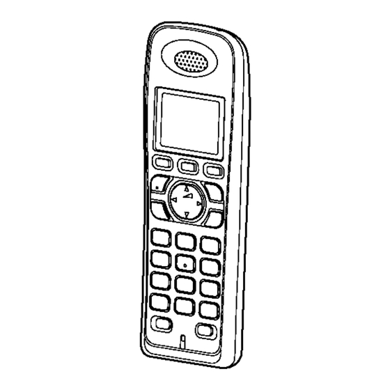
Page 14: Location Of Controls And Components
KX-TG8011MES/KX-TGA800MES 5 Location of Controls and 6 Installation Instructions Components 6.1. Connections 5.1. Controls 5.1.1. Base Unit 5.1.2. Handset... -
Page 15: Battery
KX-TG8011MES/KX-TGA800MES 6.2. Battery 6.2.2. Battery Charge 6.2.1. Battery Installation and Replacement Note for service: The battery strength may not be indicated correctly if the battery is disconnected and connected again, even after it is fully charged. In that case, by recharging the battery as mentioned above, you will get a correct indication of the battery strength. - Page 16 KX-TG8011MES/KX-TGA800MES 6.2.4. Panasonic Ni-MH Battery Performance (supplied batteries)
-
Page 17: Operating Instructions
KX-TG8011MES/KX-TGA800MES 7 Operating Instructions 7.1. Programmable Settings... -
Page 18: Registering A Handset To A Base Unit
KX-TG8011MES/KX-TGA800MES *1 The item will not be reset when pressing keys. Refer to How to Clear User Setting (P.27). *2 The item will not be reset when pressing keys. Refer to How to Clear User Setting (P.27). *3 If you select one of the melody ringer tones, the ringer tone continues to play for several seconds even if the caller has already hung up. -
Page 19: Dialling Mode (Tone/Pulse)
KX-TG8011MES/KX-TGA800MES 7.3. Dialling Mode (Tone/Pulse) 7.4. Error Messages... -
Page 20: Troubleshooting
KX-TG8011MES/KX-TGA800MES 7.5. Troubleshooting Cross Reference: For Service Hint (P.22) - Page 21 KX-TG8011MES/KX-TGA800MES...
-
Page 22: For Service Hint
KX-TG8011MES/KX-TGA800MES 7.6. For Service Hint Cross Reference: Battery Charge (P.15) -
Page 23: Service Mode
KX-TG8011MES/KX-TGA800MES 8 Service Mode 8.1. Engineering Mode 8.1.1. Base Unit... - Page 24 KX-TG8011MES/KX-TGA800MES Frequently Used Items (Base Unit) ex.) Items Address Default Data New Data Remarks C-ID (FSK) sensitivity 04 D6 01 (6dB up) 02 (12dB up) When hex changes from “00” to “01” or “02”, gain increases by 6dB or 12dB.
- Page 25 KX-TG8011MES/KX-TGA800MES 8.1.2. Handset...
- Page 26 KX-TG8011MES/KX-TGA800MES Frequently Used Items (Handset) ex.) Items Address Default Data New Data Possible Adjusted Possible Adjusted Remarks Value MAX (hex) Value MIN (hex) Sending level 00 06 Adjusted value Given value (*2) Receiving level 00 07 Adjusted value Given value...
-
Page 27: How To Clear User Setting
KX-TG8011MES/KX-TGA800MES 8.2. How to Clear User Setting Units are reset to the Factory settings by this operation (Erase stored Phone numbers, Caller list and etc.) Note: • Some menus are not reset. Refer to Operating Instructions (P.17). • The reset menus differ depending on the following operations. -
Page 28: Troubleshooting Guide
KX-TG8011MES/KX-TGA800MES 9 Troubleshooting Guide 9.1. Troubleshooting Flowchart Cross Reference: Check Power (P.29) Bell Reception (P.39) Check Battery Charge (P.30) Check Link (P.31) Check the RF Part (P.35) Check Handset Transmission (P.38) Check Handset Reception (P.38) Signal Route (P.13) Check Caller ID (P.38) -
Page 29: Check Power
KX-TG8011MES/KX-TGA800MES 9.1.1. Check Power 9.1.1.1. Base Unit Is the AC Adaptor inserted into AC outlet? (*1) Cross Reference: Note: Power Supply Circuit (P.9) (*1) Refer to Specifications (P.6) for part number and supply voltage of AC Adaptor. 9.1.1.2. Handset... -
Page 30: Check Battery Charge
KX-TG8011MES/KX-TGA800MES Cross Reference: Power Supply Circuit/Reset Circuit (P.12) 9.1.2. Check Battery Charge 9.1.2.1. Base Unit Cross Reference: Charge Circuit (P.12) 9.1.2.2. Handset Cross Reference: Check Power (P.29) Charge Circuit (P.12) -
Page 31: Check Link
KX-TG8011MES/KX-TGA800MES 9.1.3. Check Link 9.1.3.1. Base Unit Note: (*1) Refer to Troubleshooting by Symptom (Base Unit ) (P.40) Cross Reference: Check Point (Base Unit) (P.40) Power Supply Circuit (P.9) - Page 32 KX-TG8011MES/KX-TGA800MES Cross Reference: Check Point (Base Unit) (P.40)
- Page 33 KX-TG8011MES/KX-TGA800MES 9.1.3.2. Handset Note: (*1) Refer to Troubleshooting by Symptom (Handset) (P.44) Cross Reference: Check Point (Handset) (P.44) Power Supply Circuit/Reset Circuit (P.12)
- Page 34 KX-TG8011MES/KX-TGA800MES Cross Reference: Check Point (Handset) (P.44)
-
Page 35: Check The Rf Part
KX-TG8011MES/KX-TGA800MES 9.1.4. Check the RF Part 9.1.4.1. Finding out the Defective part After All the Checkings or Repairing 1. Re-register the checked Handset to the checked Base Unit, and Regular HS to Regular BU. Note: If you need to register a handset, refer to Registering a Handset to a Base Unit (P.18) - Page 36 KX-TG8011MES/KX-TGA800MES 9.1.4.2. RF Check Flowchart Each item (1 ~ 3) of RF Check Flowchart corresponds to Check Table for RF part (P.37). Please refer to the each item. Note: (*1) Base unit - refer to (G) of Check Point (Base Unit) (P.40)
- Page 37 KX-TG8011MES/KX-TGA800MES 9.1.4.3. Check Table for RF part Item BU (Base Unit) Check HS (Handset) Check Link Confirmation Normal 1. Register Regular HS to BU (to be 1. Register HS (to be checked) to Regular checked). HS, BU Mode: [Normal mode] 2.
-
Page 38: Check Handset Transmission
KX-TG8011MES/KX-TGA800MES 9.1.5. Check Handset Transmission Cross Reference: Signal Route (P.13) 9.1.6. Check Handset Reception Cross Reference: How to Check the Handset Speaker or Receiver (P.60). Signal Route (P.13) 9.1.7. Check Caller ID Cross Reference: Signal Route (P.13) -
Page 39: Bell Reception
KX-TG8011MES/KX-TGA800MES 9.1.8. Bell Reception 9.1.8.1. Base Unit 9.1.8.2. Handset Cross Reference: Telephone Line Interface (P.10) Check Link (P.31) How to Check the Handset Speaker or Receiver (P.60) -
Page 40: Troubleshooting By Symptom (Base Unit )
KX-TG8011MES/KX-TGA800MES 9.2. Troubleshooting by Symptom (Base Unit ) If your unit has below symptoms, follow the instructions in remedy column. Remedies depend on whether you have DECT tester (*1) or not. Note: (*1) A general repair is possible even if you don’t have the DECT tester because it is for confirming the levels, such as Acoustic level in detail. - Page 41 KX-TG8011MES/KX-TGA800MES Items Check Procedure Check or Point Replace Parts 1. Connect Telephone Socket to Tel-simulator which is connected with 600 Ω. (H)* Hookswitch Check with L1, L2, Q3, R14, DC Characteristics 2. Set line voltage to 48 V and line current to 40mA at off-hook condition of nor- R15, Q4, R16, mal telephone.
- Page 42 KX-TG8011MES/KX-TGA800MES Items Check Procedure Check or Point Replace Parts (M)* Frequency Drift Confir- Follow steps 1 to 6 of (J). IC7, L7, C117, mation ANTI_TP 7.Confirm that the frequency drift is < ± 20 kHz/ms. C118, C124, C125, R106, R109,DA1,...
- Page 43 KX-TG8011MES/KX-TGA800MES Items Check Procedure Check or Point Replace Parts Audio Check 1. Link with Handset. IC7, SA1, L1, 2. Input -45dBm/1kHz to MIC of Handset. L2, D3, Q3, Q4, Measure the Level at Line I/F and distortion level. R14, R15, R16, 3.
-
Page 44: Troubleshooting By Symptom (Handset)
KX-TG8011MES/KX-TGA800MES 9.3. Troubleshooting by Symptom (Handset) If your unit has below symptoms, follow the instructions in remedy column. Remedies depend on whether you have DECT tester (*1) or not. Note: (*1) A general repair is possible even if you don’t have the DECT tester because it is for confirming the levels, such as Acoustic level in detail. - Page 45 KX-TG8011MES/KX-TGA800MES Items Check Procedure Check or Point Replace Parts (F)* Battery Monitor Check 1. Apply 2.25 V between BATT+ and BATT-. IC1, F1, C1, 2. Execute the command sendchar PAD sendchar LED 0 sendchar AD1 It assumes that the return value is XX.
- Page 46 KX-TG8011MES/KX-TGA800MES Items Check Procedure Check or Point Replace Parts (K)* Frequency Offset Confir- Follow steps 1 to 3 of (I). IC1, mation 4.Confirm that the frequency Offset is < ± 20 kHz. R801~R806, C808~C814, C819, C825, C834, IC801, L802~L804, D801, R807,...
- Page 47 KX-TG8011MES/KX-TGA800MES Items Check Procedure Check or Point Replace Parts (O) Audio Check and Confir- 1. Link to BASE which is connected to Line Simulator. IC1, R23, C12, mation 2. Set line voltage to 48 V and line current to 40 mA.
-
Page 48: Disassembly And Assembly Instructions
KX-TG8011MES/KX-TGA800MES 10 Disassembly and Assembly Instructions 10.1. Disassembly Instructions 10.1.1. Base Unit... - Page 49 KX-TG8011MES/KX-TGA800MES 10.1.2. Handset...
-
Page 50: How To Replace The Handset Lcd
KX-TG8011MES/KX-TGA800MES 10.2. How to Replace the Handset LCD... -
Page 51: Measurements And Adjustments
KX-TG8011MES/KX-TGA800MES 11 Measurements and Adjustments 11.1. The Setting Method of JIG (Base Unit) 11.1.1. Preparation 11.1.1.1. Equipment Required • DECT tester: Rohde & Schwarz, CMD 60 is recommended. • Frequency counter: It must be precise enough to measure intervals of 1 Hz (precision; ±4 ppm). - Page 52 KX-TG8011MES/KX-TGA800MES 11.1.2.2. Batch file Settings Note: • “****” varies depending on the country. 11.1.2.3. Commands See the table below for frequently used commands. Command name Function Example rdeeprom Read the data of EEPROM Type “rdeeprom 00 00 FF”, and the data from address “00 00”...
-
Page 53: Adjustment Standard (Base Unit)
KX-TG8011MES/KX-TGA800MES 11.2. Adjustment Standard (Base Unit) When connecting the simulator equipment for checking, please refer to below. 11.2.1. Bottom View C149 C145 C146 R126 C156 C616 IC421 C615 C159 C624 C421 R424 R621 IC801 R652 R425 C423 R651 R650 C819... -
Page 54: The Setting Method Of Jig (Handset)
KX-TG8011MES/KX-TGA800MES 11.3. The Setting Method of JIG (Handset) 11.3.1. Preparation 11.3.1.1. Equipment Required • DECT tester: Rohde & Schwarz, CMD 60 is recommended. • Frequency counter: It must be precise enough to measure intervals of 1 Hz (precision; ±4 ppm). - Page 55 KX-TG8011MES/KX-TGA800MES 11.3.2.2. Batch file Settings Note: • “*****” varies depending on the country. 11.3.2.3. Commands See the table below for frequently used commands. Command name Function Example rdeeprom Read the data of EEPROM Type “rdeeprom 00 00 FF”, and the data from address “00 00”...
-
Page 56: Adjustment Standard (Handset)
KX-TG8011MES/KX-TGA800MES 11.4. Adjustment Standard (Handset) When connecting the simulator equipment for checking, please refer to below. 11.4.1. Component View MIC- MIC+ C113 BATT- BATT+ C150 RA61 KX-TGA800EX PNLB1040Z R330 C332 POWER CP2.5V X_CLK CP4.0V REV- SOLDER ANT1 1.8V R206 REV+... -
Page 57: Things To Do After Replacing Ic Or X'tal
KX-TG8011MES/KX-TGA800MES 11.5. Things to Do after Replacing IC or X'tal Cautions: Some of the content on this page may not apply to models from some countries. The contents below are the minimum adjust- ments required for operation. 11.5.1. Base Unit Before making the following adjustment, ensure you have carried out PC Setting (P.51) in The Setting Method of JIG (Base... - Page 58 KX-TG8011MES/KX-TGA800MES 11.5.2. Handset Before making the following adjustment, ensure you have carried out Batch file Settings (P.52) in The Setting Method of JIG (Handset). Items Necessary Adjustment BBIC (FLASH type) Programs for Voice processing, interface for RF 1. Make sure to connect the JIG cable, then detach the DC...
-
Page 59: Rf Specification
KX-TG8011MES/KX-TGA800MES 11.6. RF Specification 11.6.1. Base Unit Item Value Refer to -. * TX Power 19 dBm ~ 25 dBm Check Point (Base Unit) (J) Modulation -370±30/+370±30 kHz/div & Modulated Check Point (Base Unit) (K) width 690 kHz Frequency Offset -50 kHz ~ <+50 kHz... -
Page 60: How To Check The Handset Speaker Or Receiver
KX-TG8011MES/KX-TGA800MES 11.7. How to Check the Handset Speaker or Receiver 1. Prepare the digital voltmeter, and set the selector knob to ohm meter. 2. Put the probes at the speaker terminals as shown below. 11.8. Frequency Table (MHz) BASE UNIT... -
Page 61: Miscellaneous
KX-TG8011MES/KX-TGA800MES 12 Miscellaneous 12.1. CPU Data (Base Unit) 12.1.1. IC7 (BBIC) Pin No. Description Connection at Normal mode at Reset mode VSS_LNA1 RF_RXp RF_RXp RF_RXn RF_RXn VSS_LNA2 RFP1 RXON O_0/1 Hi-Z RFP0 ANT1 O_0/1 Hi-Z REF_RES REF_RES AVS_XTAL XTAL2 XTAL2... - Page 62 KX-TG8011MES/KX-TGA800MES Pin No. Description Connection at Normal mode at Reset mode P0_1/URX I_0/1 I-PU P0_0/UTX O_0/1 I-PU RSTn RSTn O_0/1 I-PU JTAG D.I/O JTAG I/O_0/1 I-PU P2_5/PCM_FSC/SF EEP_WP O_0/1 I-PU P2_4/SCL1/PCM_DO/ N.C. I-PU P2_3/SDA1/PCM_DI/DP2 N.C. I-PU P2_2/PCM_CLK/CLK100 N.C. I-PU P2_1/ECZ2/PWM1/LED4...
-
Page 63: Cpu Data (Handset)
KX-TG8011MES/KX-TGA800MES 12.2. CPU Data (Handset) 12.2.1. IC1 (BBIC) Pin No. Description Connection at Normal mode at Reset mode VSS_LNA1 RF_RXp RF_RXp RF_RXn RF_RXn VSS_LNA2 RFP1 RXON O_0/1 Hi-Z RFP0 ANT1 O_0/1 Hi-Z REF_RES REF_RES AVS_XTAL XTAL2 XTAL2 XTAL1 XTAL1 AVD_XTAL... - Page 64 KX-TG8011MES/KX-TGA800MES Pin No. Description Connection at Normal mode at Reset mode JTAG D.I/O JTAG I/O_0/1 I-PU P2_5/PCM_FSC/SF LCD_CSB O_0/1 I-PU P2_4/SCL1/PCM_DO/ N.C. I-PU P2_3/SDA1/PCM_DI/DP2 LCD_BACKLIT(NC) I-PU P2_2/PCM_CLK/CLK100 LCD_RESET O_0/1 I-PU P2_1/ECZ2/PWM1/LED4 N.C. P2_0/ECZ1/PWM0/LED3 BELL_LED_A VDD2 +1.8V LDORF_CTRL N.C. RF_SUPPLY2 RF_SUPPLY2...
-
Page 65: How To Replace The Flat Package Ic
KX-TG8011MES/KX-TGA800MES 12.3. How to Replace the Flat Package IC Even if you do not have the special tools (for example, a spot heater) to remove the Flat IC, with some solder (large amount), a soldering iron and a cutter knife, you can easily remove the ICs that have more than 100 pins. - Page 66 KX-TG8011MES/KX-TGA800MES 12.3.3. How to Install the IC 1. Temporarily fix the FLAT PACKAGE IC, soldering the two marked pins. *Check the accuracy of the IC setting with the corresponding soldering foil. 2. Apply flux to all pins of the FLAT PACKAGE IC.
-
Page 67: Terminal Guide Of The Ics, Transistors And Diodes
KX-TG8011MES/KX-TGA800MES 12.4. Terminal Guide of the ICs, Transistors and Diodes 12.4.1. Base Unit 12.4.2. Handset... -
Page 68: Schematic Diagram
KX-TG8011MES/KX-TGA800MES 13 Schematic Diagram 13.1. For Schematic Diagram 13.1.1. Base Unit (Schematic Diagram (Base Unit)) Notes: 1. DC voltage measurements are taken with voltmeter from the negative voltage line. 2. The schematic diagram may be modified at any time with the development of new technology. - Page 69 KX-TG8011MES/KX-TGA800MES Memo...
-
Page 70: Schematic Diagram (Base Unit)
KX-TG8011MES/KX-TGA800MES 13.2. Schematic Diagram (Base Unit) ANT1_TP ANT2_TP ANT_1 ANT_2 Beep Bell signal *R86 C122 *R87 To RF output R807 RXON GND_C C826 RX _RF 1.5p C832 RF_RXn To ANT C833 C616 C803 RF_RXp 2.5V 1.3p C801 VDD5 +2.5_CP +3.0V... - Page 71 KX-TG8011MES/KX-TGA800MES Loop Current LINE_DC *R30 100k (1005) C155 6.8k *R13 TP10 *R20 3.9k 2.2k R116 *R12 100k 5.6M +1.8V +1.8V 100k GND GND Caller ID 5.6M Bell signal RX_AF R100 K1000p 180k *R82 *R83 1.5n *C147 TX _AF K1000p 180k *C148 1.5n...
-
Page 72: Schematic Diagram (Handset)
KX-TG8011MES/KX-TGA800MES 13.3. Schematic Diagram (Handset) Charge Current BATTERY BATTERY BATT+ 5.6n 1.8V (MAX500mA) 330u 330u +1.8V 1.8V BATT- X_CLK 2.5V 4.0V CP+4.0V CP+2.5V 3.9k CHG(+) k0.1u POWER +1.8V CHG(-) GND_0 GND_1 K0.1u RSTn VBAT2 JTAG CP_C1y +1.8V LCD_CSB P2_5/PCM_FSC/SF CP_C2x... - Page 73 KX-TG8011MES/KX-TGA800MES R107 ANT_TP ANT1 R108 ANT2 R807 RXON C822 100p C827 L801 RX_RF C826 B1.5p D802 C803 RF_RXn C837 B0.5p 1.3p C832 ANT2 RF_RXp C833 CP+2.5V R806 TXON C172 BATTERY C825 0.1u VDD_PADRV R805 C812 R801 C808 100n C811 PSET...
- Page 74 KX-TG8011MES/KX-TGA800MES Memo...
-
Page 75: Printed Circuit Board
KX-TG8011MES/KX-TGA800MES 14 Printed Circuit Board 14.1. Circuit Board (Base Unit) 14.1.1. Component View R38 R39 R654 C501 R653 C163 R542 C147 R532 C148 C306 C141 C166 KX-TG8011 CIRCUIT BOARD (Base Unit (Component View)) - Page 76 KX-TG8011MES/KX-TGA800MES 14.1.2. Bottom View C149 C145 C146 R126 VDD1 C156 C616 IC421 C615 C159 C624 C421 R424 R621 IC801 R652 R425 C423 R651 R650 C819 L803 C810 R806 L804 C809 C825 C136 D801 C833 C305 C812 C820 C801 D802 C803...
-
Page 77: Circuit Board (Handset)
KX-TG8011MES/KX-TGA800MES 14.2. Circuit Board (Handset) 14.2.1. Component View ANT1 SOLDER C811 R804 R803 C804 C814 C117 C813 C183 L802 C802 C182 C808 L801 R801 C827 R805 ANT_TP JTAG C837 C46 C45 C44 C834 C187 C186 C832 R807 R203 R206 1.8V... - Page 78 KX-TG8011MES/KX-TGA800MES 14.2.2. Bottom View PNLB1040Z KX-TGA800EX C114 C103 SOFT_B SOFT_A TALK LED8 LED5 LEFT RIGHT CANCEL DOWN KX-TGA800 CIRCUIT BOARD (Handset_Main (Bottom View))
-
Page 79: Exploded View And Replacement Parts List
KX-TG8011MES/KX-TGA800MES 15 Exploded View and Replacement Parts List 15.1. Cabinet and Electrical Parts (Base Unit) -
Page 80: Cabinet And Electrical Parts (Handset)
(*1) This cable is fixed by welding. Refer to How to Replace the Handset LCD (P.50). (*2) The rechargeable Ni-MH battery HHR-4EPT or HHR-4MPT is available through sales route of Panasonic. (*3) Attatch the SPACER (No.121) to the exact location described above. -
Page 81: Accessories And Packing Materials
KX-TG8011MES/KX-TGA800MES 15.3. Accessories and Packing Materials 15.3.1. KX-TG8011MES... -
Page 82: Replacement Part List
KX-TG8011MES/KX-TGA800MES 15.4. Replacement Part List 15.4.1.2. Main P.C.Board Parts Note: 1. RTL (Retention Time Limited) (*1) When replacing IC7, IC401 or X1, make the adjustment Note: using PNZZTG8011ME. Refer to Base Unit (P.57) of The “RTL” marking indicates that its Retention Time is Things to Do after Replacing IC or X'tal. - Page 83 KX-TG8011MES/KX-TGA800MES Safety Ref. Part No. Part Name & Description Remarks Safety Ref. Part No. Part Name & Description Remarks ERJ2GEJ121 ECUE1A104KBQ 0.1 ERJ3GEYJ820 ECUE1H100DCQ 10p ERJ3GEYJ821 ECUE1A104KBQ 0.1 ERJ2GEJ104 100k ECUE1H100DCQ 10p ERJ2GEJ102 ECUE1A104KBQ 0.1 ERJ2GEJ104 100k ECUV1A225KB ERJ2GEJ102 C117...
- Page 84 KX-TG8011MES/KX-TGA800MES Safety Ref. Part No. Part Name & Description Remarks Safety Ref. Part No. Part Name & Description Remarks PNBC1003Y3 BUTTON, NAVIGATOR KEY ABS-HB PQLQR2M5N6K COIL PNJK1029Z RUBBER SWITCH (COMPONENTS PARTS) PNJT1002Z CHARGE TERMINAL (R) D1H433220001 RESISTOR ARRAY PNJT1001Z CHARGE TERMINAL (L)
- Page 85 KX-TG8011MES/KX-TGA800MES 15.4.3.1. KX-TG8011MES Safety Ref. Part No. Part Name & Description Remarks PQCUV0J106KB 10 ECUE1A104KBQ 0.1 Safety Ref. Part No. Part Name & Description Remarks ECUE0J105KBQ 1 ECUV1H103KBV 0.01 PQLV207T AC ADAPTOR ECUE1A104KBQ 0.1 PQJA10075Z CORD, TELEPHONE ECUE1H100DCQ 10p PNQX1395Z INSTRUCTION BOOK (*1) ECUE1A104KBQ 0.1...
Need help?
Do you have a question about the KX-TG8011MES and is the answer not in the manual?
Questions and answers