Table of Contents
Advertisement
Advertisement
Table of Contents

Related Manuals for Olivetti Olibook P1500


Summary of Contents for Olivetti Olibook P1500
- Page 2 October...
- Page 3 Macrovision Cor- poration. Reverse engineering or disassembly is prohibited. Intel, Celeron, and Intel Core are trademarks/registered trademarks of Intel Corporation. Olivetti and Alice are trademarks of Telecom Italia S.p.A.
-
Page 4: Important Safety Instructions
Preface IMPORTANT SAFETY INSTRUCTIONS Follow basic safety precautions, including those listed below, to reduce the risk of fire, electric shock, and injury to persons when using any electrical equipment: Do not use this product near water, for example near a bath tub, wash bowl, kitchen sink or laundry tub, in a wet basement or near a swimming pool. -
Page 5: Instructions For Care And Operation
Preface Instructions for Care and Operation The notebook computer is quite rugged, but it can be damaged. To prevent this, follow these suggestions: Don’t drop it, or expose it to shock. If the computer falls, the case and the components could be damaged. Do not expose the computer to Do not place it on an unstable Do not place anything heavy on... - Page 6 Preface Avoid interference. Keep the computer away from high capacity transformers, electric motors, and other strong magnetic fields. These can hinder proper performance and damage your data. Follow the proper working procedures for the computer. Shut the computer down properly and don’t forget to save your work.
-
Page 7: Power Safety
Preface Power Safety The computer has specific power requirements: • Only use a power adapter approved for use with this computer. • Your AC/DC adapter may be designed for international travel but it still requires a Power Safety steady, uninterrupted power supply. If you are unsure of your local power specifica- Warning tions, consult your service representative or local power company. -
Page 8: Battery Precautions
Preface Battery Precautions • Only use batteries designed for this computer. The wrong battery type may explode, leak or damage the computer. • Do not remove any batteries from the computer while it is powered on. • Do not continue to use a battery that has been dropped, or that appears damaged (e.g. bent or twisted) in any way. Even if the computer continues to work with a damaged battery in place, it may cause circuit damage, which may possibly result in fire. -
Page 9: Cleaning
Preface Cleaning Do not apply cleaner directly to the computer; use a soft clean cloth. Do not use volatile (petroleum distillates) or abrasive cleaners on any part of the computer. Servicing Do not attempt to service the computer yourself. Doing so may violate your warranty and expose you and the com- puter to electric shock. -
Page 10: Travel Considerations
Preface Travel Considerations Packing As you get ready for your trip, run through this list to make sure the system is ready to go: Check that the battery pack and any spares are fully charged. Power off the computer and peripherals. Close the display panel and make sure it’s latched. - Page 11 Preface On the Road In addition to the general safety and maintenance suggestions in this preface, and Chapter 8: Trouble- shooting, keep these points in mind: Hand-carry the notebook - For security, don’t let it out of your sight. In some areas, computer theft is very common.
- Page 12 Preface Developing Good Work Habits Developing good work habits is important if you need to work in front of the computer for long periods of time. Improper work habits can result in discomfort or serious injury from repetitive strain to your hands, wrists or other joints.
-
Page 13: Lcd Screen Care
Preface Lighting Proper lighting and comfortable display viewing angle can reduce eye strain and muscle fatigue in your neck and shoulders. • Position the display to avoid glare or reflections from overhead lighting or outside sources of light. • Keep the display screen clean and set the brightness and contrast to levels that allow you to see the screen clearly. - Page 14 Preface...
-
Page 15: Table Of Contents
Preface Contents Features & Components Notice ................ I Instructions for Care and Operation ......III Overview ..............2-1 Power Safety ............V Hard Disk Drive ............2-2 Battery Precautions ..........VI Optical (CD/DVD) Device .........2-3 Cleaning ............. VII Loading Discs ............2-3 Servicing ............. VII Handling CDs or DVDs ..........2-4 Travel Considerations ......... - Page 16 Preface Upgrading The Computer Battery Life ............3-12 Recharging the Battery Overview ..............6-1 with the AC/DC Adapter ........3-13 When Not to Upgrade ..........6-2 Battery FAQ ............3-15 Removing the Battery ..........6-3 Drivers & Utilities Upgrading the Hard Disk Drive .......6-4 Upgrading the Optical (CD/DVD) Device ....6-7 What to Install ............4-1 Upgrading the System Memory (RAM) ....6-8 Module Driver Installation ........4-2...
- Page 17 Preface Interface (Ports & Jacks) Communication ............. C-4 Power Management ..........C-4 Notebook Ports and Jacks ........A-2 Power ..............C-4 SIS Video Driver Controls Operating Systems ..........C-4 Environmental Spec ..........C-4 SIS Video Driver Installation ........B-1 Dimensions & Weight ..........C-4 SIS VGA Control Center .........B-2 Attaching Other Displays ........B-5 To Enable a Display Setting Mode ......B-6...
- Page 18 Preface...
-
Page 19: About This Concise User Guide
Please pay careful attention to the full regulatory notices and safety information contained in the present User’s Manual . © August 2009 Trademarks Intel, Celeron and Intel Core are trademarks/registered trademarks of Intel Corporation. Olivetti and Alice are trademarks/registered trademarks of Telecom Italia S.p.A. About this Concise User Guide 1 - 1... -
Page 20: Quick Start Guide
Quick Start Guide Instructions for Care and • Your AC/DC adapter may be designed for international tra- vel but it still requires a steady, uninterrupted power supply. Operation If you are unsure of your local power specifications, consult your service representative or local power company. The computer is designed for a mobile use and it is quite •... - Page 21 Quick Start Guide Servicing • Keep children away from, and promptly dispose of a damaged battery. Always dispose of batteries carefully. Attempting to service the computer yourself may violate Batteries may explode or leak if exposed to fire, or impro- your warranty and expose you and the computer to perly handled or discarded.
-
Page 22: System Startup
Quick Start Guide System Startup 1. Remove all packing materials. 2. Place the computer on a stable surface. 3. Securely attach any peripherals you want to use with the computer (e.g. keyboard and mouse) to their ports. 4. Attach the AC/DC adapter to the DC-In jack on the left of the computer, then plug the AC power cord into an outlet, and connect the AC power cord to the AC/DC adapter. -
Page 23: First Installation And Operating System Customisation
Quick Start Guide First installation and Operating System Customisation Installation of Windows Vista requires entry of certain information which is necessary for configuring and customising the operating system on the basis of user requirements. The procedure described below is valid only for the preinstalled version of Windows Vista. 1. - Page 24 Quick Start Guide 4. Enter the user name and password and choose an image to associate with the user account. The serial code can be found on the label on the If you do not enter a user name it is not possible to back of the notebook.
- Page 25 Quick Start Guide 5. At the end, after the data entered by the user is saved, the For installation of the recommended software, select the relative icon and follow the instructions provided on the screen relating to windows protection is displayed. The optimal screen.
-
Page 26: Operating System Setup
Quick Start Guide Operating System Setup If you are installing new system software, or are re-configuring your computer for a different system, make sure you configure the appropriate OS setting in the BIOS before installing a new operating system (Note: If you have installed the Windows Vista operating system with AHCI mode enabled, DO NOT disable AHCI mode or you will need to reinstall the Windows Vista OS). -
Page 27: System Software
Quick Start Guide System Software Operating Systems Supported Your computer come with system software pre- Operating Note System installed. If you are re-configuring your computer for a different For information on the Windows XP OS Windows XP with system, you will find this manual refers to the Microsoft see the Device Drivers &... -
Page 28: System Map: Front View With Lcd Panel Open
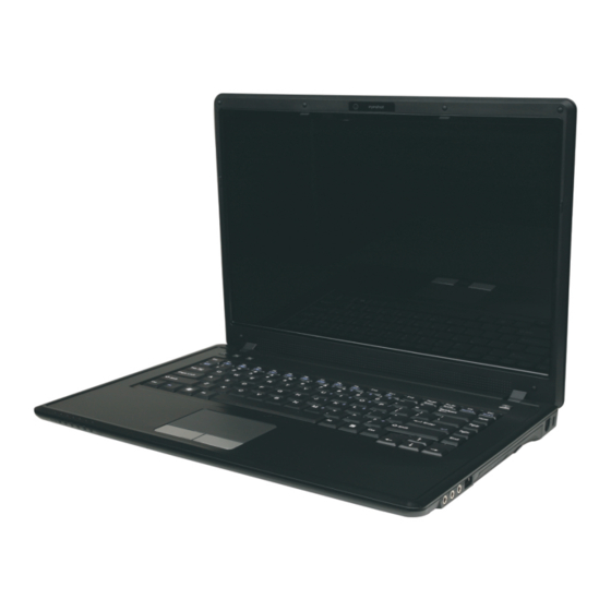
Quick Start Guide System Map: Front View with LCD Panel Figure 3 - Front View with LCD Panel Open Open 1. Built-In PC Camera 2. LCD 3. Speakers 4. Power Button 5. Hot-Key Buttons 6. Keyboard 15.4” 7. Built-In Microphone 8. -
Page 29: Hot-Key Buttons & Led Indicators
Quick Start Guide Hot-Key Buttons & LED The LED indicators on the computer display helpful information about the current status of the computer. Indicators The Hot-Key buttons give instant access to the default Icon Color Description Internet browser and e-mail program, and allow you to Orange DC Power is Plugged In toggle the Silent Mode on/off with one quick button... -
Page 30: Keyboard
Quick Start Guide Keyboard The keyboard has a numeric keypad for easy numeric data input. Pressing Fn + NumLk turns on/off the numeric keypad. It also features function keys to allow you to change operational features instantly. Keypad Function Keys NumLk &... -
Page 31: Function Keys & Visual Indicators
Quick Start Guide Function Keys & Visual Indicators The function keys (F1 - F12 etc.) will act as hot keys when pressed while the Fn key is held down. In addition to the basic function key combinations; visual indicators (see the table below) are available when the hot key utility is installed (see Table 2). -
Page 32: System Map: Front, Left, Right & Rear Views
Quick Start Guide System Map: Front, Left, Right & Rear Views Figure 5 Front, Left, Right & Rear Front Views 1. LED Indicators Left 2. DC-In Jack 3. External Monitor Port 4. RJ-45 LAN Jack 5. Vent 6. 3 * USB 2.0 Ports Right 7. -
Page 33: System Map: Bottom View
Quick Start Guide System Map: Bottom View Figure 6 Bottom View 1. Battery 2. RAM & CPU Bay Cover 3. Vent 4. Hard Disk Bay Cover 5. Bluetooth Module Cover 6. Speakers Models E & F Overheating To prevent your computer from overheating make sure nothing blocks any vent while the computer is in... -
Page 34: Video Features
Quick Start Guide Video Features This computer features SiS video options control. You can switch display devices, and configure display options, from the Display Settings control panel (in Personalization) in Windows Vista and/or the SiS VGA Control Center To access Windows Vista Display Settings: 1. -
Page 35: Power Options
Quick Start Guide Power Options Audio Features You can configure the audio options The Power Options (Hardware on your computer from the Sound and Sound menu) control panel control panel in Windows, or icon in Windows allows you to Realtek HD Audio from configure power... -
Page 36: Windows Update
Quick Start Guide Driver Installation Driver (Windows Vista with SP1) The Device Drivers & User’s Manual disc contains the Video drivers necessary for the proper operation of the computer. insert the disc and browse the Driver Folder Audio to locate the driver you need . Install it by starting the Modem executable file ( “Setup.exe”... -
Page 37: Features & Components
Features & Components Chapter 2: Features & Components Overview Read this chapter to learn more about the following main features and compo- nents of the computer: • Hard Disk Drive • Optical (CD/DVD) Device • 7-in-1 Card Reader • ExpressCard Slot •... -
Page 38: Hard Disk Drive
Features & Components Hard Disk Drive The hard disk drive is used to store your data in the computer. The hard disk Power Safety can be taken out to accommodate other 2.5" serial (SATA) hard disk drives with a height of 9.5 mm. Before attempting to ac- cess any of the internal The hard disk is accessible from the bottom of your computer as seen below. -
Page 39: Optical (Cd/Dvd) Device
Features & Components Optical (CD/DVD) Device There is a bay for a 5.25" optical (CD/DVD) device (12.7mm height) equipped Sound Volume with a . The optical device is usually labeled DVD Dual (Super Multi) Drive Module Adjustment “Drive D:” and may be used as a boot device if properly set in the BIOS (see “Boot Menu”... -
Page 40: Handling Cds Or Dvds
Features & Components Handling CDs or DVDs Proper handling of your CDs/DVDs will prevent them from being damaged. Please follow the advice below to make sure that the data stored on your CDs/ CD Emergency Eject DVDs can be accessed. If you need to manually eject a CD (e.g. -
Page 41: 7-In-1 Card Reader
Features & Components 7-in-1 Card Reader The card reader allows you to use some of the latest digital storage cards. Push Card Reader Cover the card into the slot and it will appear as a removable device, and can be ac- cessed in the same way as your hard disk (s). -
Page 42: Expresscard Slot
Features & Components ExpressCard Slot The computer is equipped with an ExpressCard/34/54 slot that reads Express ExpressCard Card/34 and ExpressCard/54 formats. ExpressCards are the successors to PCM- Slot Cover CIA (PC Cards). Make sure you install the Card Reader driver. Make sure you keep the ExpressCard/54 is used for applications which require a larger interface slot, rubber cover provided in... -
Page 43: Touchpad And Buttons/Mouse
Features & Components TouchPad and Buttons/Mouse The TouchPad is an alternative to the mouse; however, you can also add a Mouse Driver mouse to your computer through one of the USB ports. The TouchPad buttons function in much the same way as a two-button mouse. If you are using an ex- ternal mouse your oper- Once you have installed the TouchPad driver you can configure the functions... -
Page 44: Audio Features
Features & Components Audio Features You can configure the audio options on your computer from the Sound control Sound Volume panel in Windows, or from the Realtek HD Audio Manager icon in the task- Adjustment bar/control panel (right-click the taskbar icon to bring up an audio menu). -
Page 45: Power Management
Power Management Chapter 3: Power Management Overview OS Note Power management To conserve power, especially when using the battery, your computer power functions will vary slightly management conserves power by controlling individual components of the depending on your oper- computer (the monitor and hard disk drive) or the whole system. This chapter ating system. -
Page 46: The Power Sources
Power Management The Power Sources The computer can be powered by either an AC/DC adapter or a battery pack. AC/DC Adapter Use only the AC/DC adapter that comes with your computer. The wrong type of AC/DC adapter will damage the computer and its components. Attach the AC/DC adapter to the DC-in jack on the left of the computer. -
Page 47: Turning On The Computer
Power Management Turning on the Computer Now you are ready to begin using your computer. To turn it on simply press the Shut Down power button on the front panel. Note that you should al- When the computer is on, you can use the power button as a Sleep/Hibernate ways shut your computer hot-key button when it is pressed for less than 4 seconds (pressing and holding down by choosing the... -
Page 48: Power Plans
Power Management Power Plans The computer can be configured to conserve power by means of power plans. Resuming Operation You can use (or modify) an existing power plan, or create a new one. Table 3 - 1, on The settings may be adjusted to set the display to turn off after a specified page 3 - 9 for informa- time, and to send the computer into Sleep after a period of inactivity. - Page 49 Power Management Each Windows power plan will also adjust the processor performance of your machine in order to save power. This is worth bearing in mind if you are expe- riencing any reduced performance (especially under DC/battery power). Choose High performance for maximum performance when the computer is powered from an AC power source.
-
Page 50: Power-Saving States
Power Management Power-Saving States You can use power-saving states to stop the computer’s operation and restart Power Button where you left off. Sleep is the default power-saving state in Windows Vista. The Power Button Earlier versions of Windows used Stand By and Hibernate as system power- in the Start Menu (in Classic View use the Shut saving states. - Page 51 Power Management Hibernate Hibernate uses the least amount of power of all the power-saving states and saves Hibernate Mode In all of your information on a part of the hard disk before it turns the system off. If Windows Vista SP1 a power failure occurs the system can restore your work from the hard disk;...
-
Page 52: Configuring The Power Buttons
Power Management Configuring the Power Buttons The power/sleep button (Fn + F4 key combo) and closed lid may be set to send Password Protection the computer in to a power-saving state. It is recommended that you enable a password on wake up in order to protect your data. -
Page 53: Resuming Operation
Power Management Resuming Operation You can resume operation from power-saving states by pressing the power button, or in some cases pressing the sleep button (Fn + F4 key combo). Closing the Lid If you have chosen to Power Status To Resume Icon Color send the computer to... -
Page 54: Battery Information
Power Management Battery Information Please follow these simple guidelines to get the best use out of your battery. Low Battery Warning Battery Power Your computer’s battery power is dependent upon many factors, including the When the battery is criti- cally low, immediately programs you are running, and peripheral devices attached. -
Page 55: Conserving Battery Power
Power Management Conserving Battery Power • Use a power plan that conserves power (e.g Power saver), however note that this may have an affect on computer performance. • Lower the brightness level of the LCD display. The system will decrease LCD brightness slightly to save power when it is not powered by the AC/DC adapter. -
Page 56: Battery Life
Power Management Battery Life Battery life may be shortened through improper maintenance. To optimize the life and improve its performance, fully discharge and recharge the battery at least once every 30 days. We recommend that you do not remove the battery yourself. If you do need to remove the battery for any reason (e.g. -
Page 57: Proper Handling Of The Battery Pack
Power Management Proper handling of the Battery Pack • DO NOT disassemble the battery pack under any circumstances • DO NOT expose the battery to fire or high temperatures, it may explode Caution • DO NOT connect the metal terminals (+, -) to each other Danger of explosion if battery is incorrectly re- placed. -
Page 58: Battery Faq
Power Management Battery FAQ How do I completely discharge the battery? Use the computer with battery power until it shuts down due to a low battery. Don’t turn off the computer even if a message indicates the battery is critically low, just let the computer use up all of the battery power and shut down on its own. - Page 59 Power Management Scroll down to Battery and click + to expand the battery options. Choose the options below (click Yes if a warning appears): Figure 3 - 7 Power Options Advanced Settings - Battery • Low battery levels = 0% •...
- Page 60 Power Management How do I fully charge the battery? When charging the battery, don’t stop until the LED charging indicator light changes from orange to green. How do I maintain the battery? Completely discharge and charge the battery at least once every 30 days or af- ter about 20 partial discharges.
-
Page 61: Drivers & Utilities
Drivers & Utilities Chapter 4: Drivers & Utilities What to Install This chapter deals with installing the drivers and utilities essential to the operation or improvement The Device Drivers & User’s Manual disc contains of some of the computer’s subsystems. The system the drivers necessary for the proper operation of the takes advantage of some newer hardware compo- computer. -
Page 62: Module Driver Installation
Drivers & Utilities Module Driver Installation The procedures for installing drivers for the Wireless From “my Computer” select the CD/DVD unit con- LAN and PC Camera modules are provided in tainning the Device Drivers & User’s Manual disc. RightClick and select Browse . “Modules &... -
Page 63: Updating/Reinstalling Individual Drivers
Drivers & Utilities Updating/Reinstalling Individual Drivers Windows Update After installing all the drivers make sure you enable If you wish to update/reinstall individual drivers it Windows Update in order to get all the latest se- may be necessary to uninstall the original driver.To curity updates etc. -
Page 64: User Account Control (Win Vista)
Drivers & Utilities User Account Control (Win Vista) Windows Security Message If a User Account Control prompt appears as part If you receive a Windows security message as part of the driver installation procedure, click Continue of the driver installation process. Just click “Install or Allow, and follow the installation procedure as this driver software anyway”... -
Page 65: New Hardware Found
Drivers & Utilities New Hardware Found USB Hotfix If you see the message “New Hardware Found” In order to resolve issues with USB devices (internal & external) in 4GB Windows Vista systems we during the installation procedure (other than when outlined in the driver install procedure), recommend that you install the USB hotfix driver click Cancel to close the window, and follow the provided (see... - Page 66 Drivers & Utilities 4 - 6 What to Install...
-
Page 67: Bios Utilities
BIOS Utilities Chapter 5: BIOS Utilities Overview BIOS Settings Warning This chapter gives a brief introduction to the computer’s built-in software: Incorrect settings cause your system to Diagnostics: The POST (Power-On Self Test) malfunction. To correct mistakes, return to Setup Configuration: The Setup utility and restore the Setup Defaults with <F9>. -
Page 68: The Power-On Self Test (Post)
BIOS Utilities The Power-On Self Test (POST) Each time you turn on the computer, the system takes a few seconds to con- POST Screen duct a POST, including a quick test of the on-board RAM (memory). As the POST proceeds, the computer will tell you if there is anything wrong. If 1.BIOS information there is a problem that prevents the system from booting, it will display a sys- 2.CPU type... -
Page 69: Failing The Post
BIOS Utilities Failing the POST Errors can be detected during the POST. There are two categories, “fatal” and “non-fatal”. Fatal Errors These stop the boot process and usually indicate there is something seriously wrong with your system. Take the computer to your service representative or authorized service center as soon as possible. -
Page 70: The Setup Program
BIOS Utilities The Setup Program The Phoenix Setup program tells the system how to configure itself and man- age basic features and subsystems (e.g. port configuration). Entering Setup To enter Setup, turn on the computer and press F2 during the POST. The prompt (Press F2 to Enter Setup) seen on page 5 - 2 is usually present for a... -
Page 71: Setup Screens
BIOS Utilities Setup Screens The following pages contain additional advice on portions of the Setup. Setup Menus Along the top of the screen is a menu bar with menu headings. When you se- The Setup menus shown lect a heading, a new screen appears. Scroll through the features listed on each in this section are for ref- screen to make changes to Setup. -
Page 72: Main Menu
BIOS Utilities Main Menu PhoenixBIOS Setup Utility Figure 5 - 2 Main Main Advanced Security Boot Exit Main Menu Item Specific Help System Time: [22:12:05] System Date: [08/23/2008] IDE Channel 0 Master [None] <Tab>, <Shift Tab>, or SATA Port 1 [FUJITSU MHV2100BH PL] <Enter>... - Page 73 BIOS Utilities IDE Channel 0 Master (Main Menu) Pressing Enter opens the sub-menu to show the configuration of an optical De- vice/HDD on the computer’s IDE Channel. Use the Auto (Type:) setting to have the items configured automatically for you. SATA Port 1/2 (Main Menu) Pressing Enter opens the sub-menu to show the configuration of a optical De- vice/HDD on the computer’s SATA Port 1/2.
-
Page 74: Advanced Menu
BIOS Utilities Advanced Menu PhoenixBIOS Setup Utility Main A A dvanced Advanced Security Boot Exit Item Specific Help Installed O/S: [VISTA] SATA Mode Selection: [AHCI] Select the operating Legacy USB Support: [Enabled] system installed Boot-time Diagnostic Screen: [Disabled] on your system which Reset Configuration Data: [Yes] you will use most... - Page 75 BIOS Utilities SATA Mode Selection (Advanced Menu) This menu is only available if you select the Vista O/S as your operating system. You can configure SATA (Serial ATA) control to operate in either IDE (native/ compatible) or AHCI (Advanced Host Controller Interface) modes from this menu.
- Page 76 BIOS Utilities Power on Boot Beep (Advanced Menu) Use this menu item to enable/disable the beep as the computer starts up. Battery Low Alarm Beep (Advanced Menu) Use this menu item to enable/disable the battery low alarm beep. Embedded Shared Memory (Advanced Menu) Use this menu item to change the amount of shared memory available (128MB OR 256MB) to the graphics system for SiS video only 5 - 10 Advanced Menu...
-
Page 77: Security Menu
BIOS Utilities Security Menu PhoenixBIOS Setup Utility Security Menu S e c ur i t y Main Advanced S S e e c c u u r r i i t t y y Boot Exit I t em Spec i f i c Hel p The changes you make Supervisor Password Is: Clear... - Page 78 BIOS Utilities Set User Password (Security Menu) You can set a password for user mode access to the PhoenixBIOS Setup Util- ity. This will not affect access to the computer OS, (only the Setup utility) un- Password Warning less you choose to set a Password on Boot (see below). Many menu items in the PhoenixBIOS Setup Utility cannot be modified in user mode.
-
Page 79: Boot Menu
BIOS Utilities Boot Menu PhoenixBIOS Setup Utility Figure 5 - 5 Main Advanced Security Boot Exit Boot Menu Item Specific Help Boot priority order: IDE CD: TSSTcorp CDDVD TS-L633A Keys used to view or IDE HDD: FUJITSU MHV2160BH-(S1) configure devices: USB KEY: Up and Down arrows USB FDC:... -
Page 80: Exit Menu
BIOS Utilities Exit Menu Figure 5 - 6 PhoenixBIOS Setup Utility Main Advanced Security Boot Exit Exit Menu Item Specific Help Exit Saving Changes Exit Discarding Changes Exit System Setup and Load Setup Defaults save your changes to Discard Changes CMOS. -
Page 81: Upgrading The Computer
Upgrading The Computer Chapter 6: Upgrading The Computer Overview This chapter contains information on upgrading the computer. Follow the steps Warranty Warning outlined to make the desired upgrades. If you have any trouble or problems you can contact your service representative for further help. Before you begin you Please check with your will need: service representative be-... -
Page 82: When Not To Upgrade
Upgrading The Computer When Not to Upgrade These procedures involve opening the system’s case, adding and sometimes re- placing parts. Power Safety Warning You should not perform any of these upgrades if: Before you undertake • Your system is still under warranty or a service contract any upgrade procedures, •... -
Page 83: Removing The Battery
Upgrading The Computer Removing the Battery If you are confident in undertaking upgrade procedures yourself, for safety rea- Warranty Warning sons it is best to remove the battery. Turn the computer off, and turn it over. Please check with your service representative be- Slide the latch in the direction of the arrow. -
Page 84: Upgrading The Hard Disk Drive
Upgrading The Computer Upgrading the Hard Disk Drive The hard disk drive can be taken out to accommodate other 2.5" serial (SATA) HDD System hard disk drives with a height of 9.5mm (h). Warning Follow your operating system’s installation instructions, and install all necessary drivers and utilities (see “Driver Installation”... - Page 85 Upgrading The Computer Grip the tab and slide the hard disk in the direction of arrow Lift the hard disk out of the bay Figure 6 - 2 HDD Removal Upgrading the Hard Disk Drive 6 - 5...
- Page 86 Upgrading The Computer Remove the screw(s) & and the adhesive cover (depending on your model type/design). Reverse the process to install a new hard disk drive (do not forget to replace all the screws and covers). Figure 6 - 3 HDD Cover Removal Hard Disk Screws &...
-
Page 87: Upgrading The Optical (Cd/Dvd) Device
Upgrading The Computer Upgrading the Optical (CD/DVD) Device Turn off the computer, and turn it over and remove the battery. Locate the hard disk bay cover and loosen screws & Fan Cable & Cover Remove the hard disk bay cover Make sure you recon- nect the fan cable before screwing down... -
Page 88: Upgrading The System Memory (Ram)
Upgrading The Computer Upgrading the System Memory (RAM) The computer has two memory sockets for 200 pin Small Outline Dual In-line (SO-DIMM) DDRII (DDR2) type memory modules (see “Appendix C” for de- tails of supported module types). Turn off the computer, and turn it over and remove the battery. Locate the RAM &... - Page 89 Upgrading The Computer Carefully (a fan and cable are attached to the under side of the cover) lift up the bay cover. Carefully disconnect the fan cable , and remove the cover Figure 6 - 6 CPU/RAM Bay Cover Removed Fan Cable Make sure you reconnect the fan cable before screwing down the bay cover.
- Page 90 Upgrading The Computer Gently pull the two release latches on the sides of the memory socket in the direction indicated by the arrows ( & Figure 6 - Figure 6 - 7 RAM Module Release Latches 6 - 10 Upgrading the System Memory (RAM)
- Page 91 Upgrading The Computer The RAM module will pop-up, and you can remove it. Figure 6 - 8 RAM Module Removal Pull the latches to release the second module if necessary. Insert a new module holding it at about a 30° angle and fit the connectors firmly into the memory slot.
- Page 92 Upgrading The Computer 11. Replace the bay cover (see sidebar) and screws (make sure you reconnect the fan cable before screwing down the bay cover). Figure 6 - 9 Cover Pin Alignment Cover Pins Note that Model B & D four computers have...
-
Page 93: Additional Modules
Additional Modules Chapter 7: Additional Modules Overview Wireless Device Operation Aboard This chapter contains information on the following modules, which come with Aircraft your computer. The use of any portable elec- • Bluetooth Module tronic transmission devices • PC Camera Module aboard aircraft is usually •... -
Page 94: Bluetooth Module
Additional Modules Bluetooth Module The operating system’s Bluetooth Devices control panel is used to configure Wireless Device the Bluetooth settings in Windows Vista, and therefore does not require a Operation Aboard driver. Use the Fn + F12 key combination to toggle power to the Blue- Aircraft tooth module. -
Page 95: Bluetooth Configuration In Windows Vista
Additional Modules Bluetooth Configuration in Windows Vista Setup your Bluetooth Device so the Computer Can Find it Turn your Bluetooth device (e.g. PDA, mobile phone etc.) on. Bluetooth Taskbar Make the device discoverable (to do this check your device documentation). Icon If you cannot see the To Turn the Bluetooth Module On... - Page 96 Additional Modules To Add a Bluetooth Device Access the Bluetooth Devices control panel. Click Options (tab), and make sure that Allow Bluetooth devices to connect to this computer check box (Connections) has a tick inside it. Click Devices (tab), and then click Add. The Add Bluetooth Device Wizard will appear.
- Page 97 Additional Modules To Change Settings for the Bluetooth Device Access the Bluetooth Devices control panel. Click on the device you want to change and click Properties to: Bluetooth Help • Change the name of the device (click General, type a new name and click OK). •...
-
Page 98: Pc Camera Module
Additional Modules PC Camera Module Before installing the PC Camera driver, make sure that the optional PC Camera Latest PC Camera is on. Use the Fn + F10 key combination to toggle power to the PC Cam- Driver Information era module. Make sure you install the drivers in the order indicated in Table 4 - 1, on page 4 - 2 Check the Device Drivers... -
Page 99: Pc Camera Driver Installation
Additional Modules PC Camera Driver Installation 1. IMake sure the module is powered on, and then insert the Device Drivers & User’s Manual disc into the CD/DVD drive. PC Camera Screen 2. Browse the CD and go to the Drivers / Camera folder . Refresh 3. - Page 100 Additional Modules PC Camera Audio Setup If you wish to capture video & audio with your camera, it is necessary to setup the audio recording options in Windows. Click Start, and click Control Panel (or point to Settings and click Control Panel). Click Sound (Hardware and Sound).
- Page 101 Additional Modules Figure 7 - 5 Audio Setup for PC Camera Right-click PC Camera Module 7 - 9...
- Page 102 Additional Modules BisonCap BisonCap is a video viewer for general purpose video viewing and testing, and for capturing video files to .avi format. Run the BisonCap application (it is recommended that you set the capture file before the capture process - see “Set Capture File”...
- Page 103 Additional Modules Reducing Video File Size Note that capturing high resolution video files requires a substantial amount of disk space for each file. After recording video, check the video file size (right-click the file and select Properties) and the remaining free space on your hard disk (go to My Computer, right-click the hard disk, and select Properties).
- Page 104 Additional Modules Eliminating Screen Flicker If you find that the video screen in the BisonCap program is flickering, you can try to adjust the setting in the Video Capture Filter options. Run the BisonCap application program from the desktop shortcut. Go to Options and scroll down to select Video Capture Filter..
- Page 105 Additional Modules Zoom The BisonCapprogram allows you to zoom the camera in and out. Run the BisonCap application program from the desktop shortcut. Go to Zoom and select Zoom Out/Zoom In. Figure 7 - 7 Zoom/Setting Snapshot Folder Taking Still Pictures In BisonCap the Snapshot The BisonCap program allows you to take still pictures.
-
Page 106: Wireless Lan Module
Additional Modules Wireless LAN Module Make sure that the Wireless LAN module is on before installing the driver. Wireless Device Operation Aboard Use the Fn + F11 key combination (see “Function/Hot Key Indicators” on Aircraft Chapter 1) to toggle power to the Wireless LAN module. Make sure you in- stall the drivers in the order indicated in Table 4 - 1, on page 4 - 2 The use of any portable elec-... -
Page 107: Connecting To A Wireless Network
Additional Modules Connecting to a Wireless Network Make sure the Wireless LAN module is turned on. Click the taskbar wireless icon , and then click Connect to a network (or right- click the icon , and then click Connect to a network). Figure 7 - 8 Taskbar Menus Right-click icon... - Page 108 Additional Modules Click a network, and then click Connect. If you do not see a network you want to connect to, click Set up a connection or network (a list of options will appear allowing manual searching, and creating a new network).
- Page 109 Additional Modules To disconnect from the wireless network you can click the taskbar wireless icon and then select Connect or disconnect to access the network menu, and click Disconnect (or right-click the icon , and then click Disconnect from). Security Enabled Networks You should try to make sure that any network you are...
- Page 110 Additional Modules Windows Mobility Center The Windows Mobility Center control panel provides an easy point of access for information on battery status, power plans used and wireless device status etc. To access the Windows Mobility Center: Click Start, and click Control Panel (or point to Settings and click Control Panel). Double-click Windows Mobility Center (Mobile PC).
-
Page 111: Troubleshooting
Troubleshooting Chapter 8: Troubleshooting Overview Should you have any problems with your computer, before consulting your service representative, you may want to try to solve the problem yourself. This chapter lists some common problems and their possi- ble solutions. This can’t anticipate every problem, but you should check here before you panic. If you don’t find the answer in these pages, make sure you have followed the instructions carefully and observed the safety precautions in the preface. -
Page 112: Basic Hints And Tips
Troubleshooting Basic Hints and Tips Many of the following may seem obvious but they are often the solution to a problem when your com- puter appears not to be working. • Power - Is the computer actually plugged into a working electrical outlet? If plugged into a power strip, make sure it is actually working. -
Page 113: Backup And General Maintenance
Troubleshooting Backup and General Maintenance • Always backup your important data, and keep copies of your OS and programs safe, but close to hand. Don’t forget to note the serial numbers if you are storing them out of their original cases, e.g. in a CD wallet. -
Page 114: Viruses
Troubleshooting Viruses • Install an Anti-Virus program and keep the definitions file (the file which tells your program which viruses to look for) up to date. New computer viruses are discovered daily, and some of them may seri- ously harm your computer and cause you to lose data. Anti-Virus programs are commercially avail- able and the definitions file updates are usually downloadable directly from the internet. -
Page 115: Upgrading And Adding New Hardware/Software
Troubleshooting Upgrading and Adding New Hardware/Software • Do not be tempted to make changes to your Windows Registry unless you are very sure of what you are doing, otherwise you will risk severely damaging your system. • Don’t open your computer or undertake any repair or upgrade work if you are not comfortable with what you are doing. - Page 116 Troubleshooting • Thoroughly check any recent changes you made to your system as these changes may affect one or more system components, or software programs. If possible, go back and undo the change you just made and see if the problem still occurs. •...
-
Page 117: Problems And Possible Solutions
Troubleshooting Problems and Possible Solutions Problem Possible Cause - Solution You turned on the power but it doesn’t Battery missing / incorrectly installed. Check the battery bay, make sure the battery work. is present and seated properly (the design of the battery only allows it to go in one way). - Page 118 Troubleshooting Problem Possible Cause - Solution The computer feels too hot. Make sure the computer is properly ventilated and the Vent/Fan intakes are not blocked. If this doesn’t cool it down, put the system into Hibernate mode or turn it off for an hour. Make sure the computer isn’t sitting on a thermal surface . Make sure you’re using the correct adapter.
- Page 119 Troubleshooting Problem Possible Cause - Solution You forget the boot password. If you forget the password, you may have to discharge the battery of the CMOS. Contact your service representative for help. Password Warning If you choose to set a boot password, NEVER forget your password. The consequences of this could be serious. If you cannot remember your boot password you must contact your vendor and you may lose all of the information on your hard disk.
- Page 120 Troubleshooting Problem Possible Cause - Solution Other Keyboards If your keyboard is damaged or you just want to make a change, you can use any standard USB keyboard. The system will detect and enable it automatically. However special functions/hot keys unique to the system’s regular keyboard may not work.
- Page 121 Troubleshooting Problem Possible Cause - Solution Wireless LAN/Bluetooth/ The driver(s) for the module(s) have not been installed. Make sure you have Camera/ modules cannot be configured. installed the driver for the appropriate module (see the instructions for the appropriate module in “Modules &...
- Page 122 Troubleshooting Problem Possible Cause - Solution The Hibernate function has disappeared. You have a computer with 4GB of RAM and have installed Windows Vista Service Pack 1. This is a known issue if your computer has 4GB of RAM and is running Win- dows Vista Service Pack 1.
- Page 123 Troubleshooting Problem Possible Cause - Solution USB Hotfix You have a computer with 4GB of RAM and are having problems with USB devices (with both internal and external USB devices). This is a known issue and can be re- The computer’s USB devices “hang” solved by installing the USB hotfix provided on the Device Drivers &...
-
Page 124: Screen Resolution Error
Troubleshooting Screen Resolution Error If you are experiencing either screen resolution reduction, or screen flickering after resuming from Sleep in Windows Vista only then follow the instructions below to fix this problem. This error arises in compliance with Windows Vista policy, which triggers TMM (Transient Multi-Monitor Manager) when the notebook lid (S3) is closed. - Page 125 Troubleshooting Click MobilePC to open the control panel. Right-click TMM and select Disable. - TMM Disable Figure 8 - 2 Close all the control panels. Screen Resolution Error 8 - 15...
- Page 126 Troubleshooting 8 - 16...
-
Page 127: Interface (Ports & Jacks)
Interface (Ports & Jacks) Appendix A: Interface (Ports & Jacks) Overview The following chapter will give a quick description of the interface (ports & jacks) which allow your com- puter to communicate with external devices, connect to the internet etc. Interface (Ports &... -
Page 128: Notebook Ports And Jacks
Interface (Ports & Jacks) Notebook Ports and Jacks Item Description Card Reader Port The card reader allows you to use some of the latest digital storage cards. Push the card into the slot and it will appear as a removable device. DC-In Jack Plug the supplied AC/DC adapter into this jack to power your computer. - Page 129 Interface (Ports & Jacks) Item Description RJ-45 LAN Jack This port supports LAN (Network) functions. Note: Broadband (e.g. ADSL) modems usually connect to the LAN port. Security Lock Slot To prevent possible theft, a Kensington-type lock can be attached to this slot. Locks can be purchased at any computer store.
- Page 130 Interface (Ports & Jacks) A - 4...
-
Page 131: Sis Video Driver Controls
Appendix B: SIS Video Driver Controls The basic settings for configuring the LCD are outlined in section1. SIS Video Driver Installation Function Key Combination 1. Insert the Device Drivers & User’s Manual disc into the CD/DVD You can use the Fn + F7 drive. -
Page 132: Sis Vga Control Center
SIS VGA Control Center More advanced video configuration options are provided by the SIS VGA Con- trol Center. Click Start, and click Control Panel (or point to Settings and click Control Panel). Double-click SiS VGA Control Center (click “Classic View” from the left of the menu if you are in Control Panel Home). - Page 133 You may make changes to the video and display settings by clicking the appro- priate menu button. Figure B - 2 SIS VGA Control Center Control Panels SIS VGA Control Center B - 3...
- Page 134 Display Devices & Options Besides the built-in LCD, you can also use an external VGA monitor (CRT) or external Flat Panel Display as your display device. A VGA monitor/Flat Panel Display connects to the external monitor port. The following display modes are available.
-
Page 135: Attaching Other Displays
Attaching Other Displays Besides the built-in LCD, you can also use an external monitor (CRT)/flat panel display as your display device. Connect it to the external monitor port on the left of the computer, and configure the displays from SiS VGA Control Cen- ter : Attach your external display to the external monitor port and turn it on. -
Page 136: To Enable A Display Setting Mode
You can then choose the Display Setting mode from the menu buttons. Figure B - 5 Confirm Changes To Enable a Display Setting Mode Attach your external display to the external monitor port and turn it on. Go to the SiS VGA Control Center > Display Setting menu Click the appropriate icon for the display setting mode you wish to use. - Page 137 Click Apply > Yes to save any changes. Display Settings Extended Desktop Multi-Mode Clone Use the control panel to drag the monitors to match the physical ar- rangement you wish to use. You can drag any icons or windows across to ei- ther display desktop,...
- Page 138 ), and make sure you have checked “Extend the Click the monitor icon (e.g. desktop onto this monitor.” and click Apply. Click the appropriate monitor icon (e.g. ) to be able to select the option to extend the desktop on to it. In this example the Primary Dis- play is on the left, the Second-...
-
Page 139: Specifications
Specifications Appendix C: Specifications Latest Specification Information The specifications listed in this Appendix are correct at the time of going to press. Certain items (particularly processor types/ speeds and CD/DVD device types) may be changed, delayed or updated due to the manufacturer's release schedule. Check with your service center for details. -
Page 140: Processor
Specifications Feature Specification Processor Intel® Core™2 Duo Processor 45nm (45 Nanometer) Process Technology (478-pin) Micro-FC-PGA Package, Socket P 2MB On-die L2 Cache & 800MHz FSB - TDP 35W T6400 or higher 2.0 GHz Core Logic SiS M672 + SiS968 Chipset 15.4"... -
Page 141: Bios
Specifications Feature Specification BIOS One 8Mb SPI Flash ROM Phoenix™ BIOS Storage One Changeable 12.7mm(h) DVD Dual (Super Multi) Drive Module ; Easy Changeable 2.5" 9.5 mm (h) SATA (Serial) HDD Audio High Definition Audio (HDA) S/PDIF Digital Output 3D Stereo Enhanced Sound System 2 * Built-In Speakers Built-In Microphone Keyboard... -
Page 142: Communication
Specifications Feature Specification Communication 56K Fax Modem Built-In 10M/100Mb Base-TX Ethernet LAN 802.11b/g Wireless LAN Mini-Card Module with USB interface 1.3M or 2.0M Pixel USB PC Camera Module Bluetooth 2.1 + EDR (Enhanced Data Rate) Module Power Supports ACPI 3.0 Supports Wake on USB Management Supports Wake on LAN...
Need help?
Do you have a question about the Olibook P1500 and is the answer not in the manual?
Questions and answers