Table of Contents
Advertisement
Quick Links
Advertisement
Table of Contents

Related Manuals for Clarke BARREL


Summary of Contents for Clarke BARREL
-
Page 1: User Guide
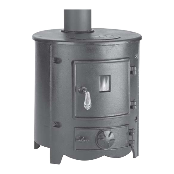
Classic Cast Iron Stove BARREL PART NO: 6910100 USER GUIDE GC0711... -
Page 2: Product Specification
Please note that details and specifications contained herein, are correct at the time of going to print. All data is applicable to wood burning use only. CLARKE International reserve the right to change specifications at any time without prior notice. -
Page 3: Installation Of This Product
INSTALLATION OF THIS PRODUCT WARNING! AN ACCREDITED HEATING ENGINEER MUST CARRY OUT THE INSTALLATION OF THIS STOVE. ALTERNATIVELY, SHOULD A NON- ACCREDITED ENGINEER UNDERTAKE THE INSTALLATION, YOUR LOCAL BUILDING CONTROL OFFICER WILL BE REQUIRED TO APPROVE THE COMPLETED INSTALLATION UNDER BUILDING REGULATION “J”. IT IS AN OFFENCE UNDER UK LAW, NOT TO COMPLY WITH THIS MANDATORY REQUIREMENT. -
Page 4: General Safety Rules
THIS STOVE MUST BE CONNECTED TO A SUITABLE FLUE OUTLET. Due to high temperature this stove should be located well away from furniture and curtains. Children and adults should be alerted to the hazards of hot surfaces. Young children should be carefully supervised when they are in the same room as the stove. -
Page 5: Unpacking And Assembly
Before assembling, please check contents against the following list and advise your dealer immediately if any parts are missing. Refer to parts list and diagram on pages 21 & 22. 1 x Barrel Stove 1 x Ash Box 1 x Fixings Kit... -
Page 6: Positioning And Installation
POSITIONING AND INSTALLATION In England and Wales, there are only two routes to legally install a domestic solid fuel or wood burning appliance. In other parts of the UK there are variations in legislation and processes. You can either: • Use a registered installer who can self certify that the work he does complies with the relevant Building Regulations;... -
Page 7: Material Clearances
MATERIAL CLEARANCES The stove must have a minimum clearance of 1200 mm to a combustible ceiling above. Fig 3 It is recommended that the stove be installed at least 600 mm from combustible materials. However, any household furnishings should be at least 1000 mm away as they could be adversely affected by heat. - Page 8 Building Regulations document “J” A range of suitable flue pipes, cowls and fire cement are available from your Clarke dealer. Special methods are required when passing through a wall or ceiling. Please refer to your local building regulations and/or fire department. Refer to Building Regulations Document “J”.
- Page 9 Fig 4 As an alternative approach, the calculation procedure within BS EN 13384- 1:2005 can be used as the basis for deciding whether a chimney design will provide sufficient draught. If in doubt, consult the Building Regulations. The outlet from a flue should be above the roof of the building in a position where the products of combustion can discharge freely and will not present a fire hazard, whatever the wind conditions.
-
Page 10: Inspection And Cleaning
INSPECTION & CLEANING Check that the chimney is in good condition, dry and free from cracks and obstructions. The diameter of the chimney should not be less than 150mm and not more than 230mm. If any of these requirements are not met, the chimney should be lined by a suitable method. -
Page 11: Connection To The Chimney
i l i > t s r s i l i i l i < i l i > s i l i i l i < CONNECTION TO THE CHIMNEY This MUST be carried out by an accredited/competent person and/or approved by your local Building Control Officer before using the stove. - Page 12 Fig 6: Horizontal register plate Fig 5: Horizontal register plate with optional vertical rear flue with top flue connection connection A non-combustible register plate minimum 1.5 mm thick should be fitted to all installations between the flue and the building structure. It’s suitability and fit should be checked by a qualified stove installation engineer against the current Building Regulations “J”.
-
Page 13: Cleaning The Flue
(e.g. a soot door or access through a register plate). Purpose-made soot doors and inspection lengths are available from the Clarke range. Ensure that the whole length of the flue can be reached from the soot door. -
Page 14: Carbon Monoxide Alarms
CARBON MONOXIDE ALARMS Due consideration should be given to the dangers of carbon monoxide poisoning following incomplete combustion of solid fuels in an enclosed space. Carbon monoxide detectors to BS EN 50291 are available for use in domestic premises and details are available in the official HETAS guide that can be viewed on their website at www.hetas.co.uk. -
Page 15: Types Of Fuel
WARNING: THE TEMPERATURE REACHED BY THESE ITEMS DURING OPERATION MAY CAUSE AN INJURY TO AN END-USER. AS THESE ARE INTENDED TO BE ADJUSTED DURING OPERATION, IT IS RECOMMENDED THAT PROTECTIVE GLOVES ARE WORN WHEN HANDLING THESE PARTS. TYPES OF FUEL A mixture of fuels can be used in conjunction with wood, provided the base of the fire remains as wood or compressed block fuels. -
Page 16: Initial Seasoning
The UK Smoke Control Areas web-site (http:/ www.uksmokecontrolareas.co.uk) defines the location of smoke controlled areas throughout England, Scotland, Wales and Northern Ireland and lists all fuels which are authorised for use in Smoke Control Areas. INITIAL SEASONING Following installation, and before regular use, the stove must be seasoned to prevent cracking of the metal casting. -
Page 17: Ash Removal
Be sure to remove the ash when the fire is at its lowest point, such as first thing in the morning. The Ash Can Filter is ideal for use in conjunction with the Clarke range of vacuum cleaners, for collecting hot ash and debris from stoves. -
Page 18: Troubleshooting
TROUBLESHOOTING f f i . t r t i l , l l n i l t i l . s l . y l y l l i l i , s t n i l l i t l i t . -
Page 19: General Maintenance
Wait until the stove has cooled down before doing this. This finish can be renovated with Clarke stove paint, although the paint may not be an exact match and it may be necessary to repaint the complete stove. - Page 20 GLASS PANELS Clean any glass panels when cool, avoiding abrasive substances which could scratch the glass and make subsequent cleaning more difficult. Wet logs against a heated glass, a badly aimed poker or heavy slamming of the doors could crack the glass panels. The glass will not fracture with heat. Never replace any broken glass with glass NOT approved for use with cast iron stoves.
-
Page 21: Parts Diagram
PARTS DIAGRAM IMPORTANT: The use of parts other than CLARKE replacement parts may result in safety hazards, decreased appliance performance and may invalidate your warranty. -
Page 22: Component Parts List
COMPONENT PARTS LIST v i l ACCESSORIES Refer to the Clarke website www.clarkeinternational.com for a full range of Flue Pipes & Cowls for use with this classic cast iron stove. See also the following accessories; Fire Cement (1Kg tubs) Part No: 6910000... -
Page 23: Declaration Of Conformity
DECLARATION OF CONFORMITY...
Need help?
Do you have a question about the BARREL and is the answer not in the manual?
Questions and answers