Table of Contents
Advertisement
Quick Links
Advertisement
Table of Contents

Related Manuals for Clarke Victoria


Summary of Contents for Clarke Victoria
-
Page 1: User Guide
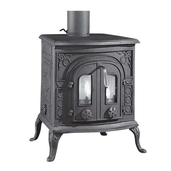
Classic Cast Iron Stove VICTORIA PART NO: 6910030 USER GUIDE GC12/11... -
Page 2: Product Specification
Please note that details and specifications contained herein, are correct at the time of going to print. All data is applicable to wood burning use only. CLARKE International reserve the right to change specifications at any time without prior notice. -
Page 3: Installation Of This Product
INSTALLATION OF THIS PRODUCT WARNING! AN ACCREDITED HEATING ENGINEER MUST CARRY OUT THE INSTALLATION OF THIS STOVE. ALTERNATIVELY, SHOULD A NON- ACCREDITED ENGINEER UNDERTAKE THE INSTALLATION, YOUR LOCAL BUILDING CONTROL OFFICER WILL BE REQUIRED TO APPROVE THE COMPLETED INSTALLATION. IT IS AN OFFENCE UNDER UK LAW, NOT TO COMPLY WITH THIS MANDATORY REQUIREMENT. -
Page 4: General Safety Rules
THIS STOVE MUST BE CONNECTED TO A SUITABLE FLUE OUTLET. Due to high temperature this stove should be located well away from furniture and curtains. Children and adults should be alerted to the hazards of hot surfaces. Young children should be carefully supervised when they are in the same room as the stove. -
Page 5: Unpacking And Assembly
WARNING: DUE TO THE WEIGHT OF THE STOVE IT IS ESSENTIAL THAT TWO PEOPLE PERFORM THE UNPACKING, ASSEMBLY & POSITIONING. The Victoria stove is attached to the wooden pallet by two 12mm bolts, screwed into the base of the stove from underneath. These will need to be removed before the stove can be freed from the crate and other packaging materials. -
Page 6: Positioning And Installation
3. Attach the chimney flue Fig 2 connector as shown in Fig 2 using the x-headed bolts & nuts supplied. Ensure the fireproof gasket is correctly seated in the recess. 4. Install the blanking plate to the rear panel of the stove when the normal flue exit is required. -
Page 7: Supporting Floors
For specific guidancewhen cast iron stoves are being installed in boats and homes with thatched roofs, please refer to the SOLIFTEC website at; www.soliftec.com/installation.htm SUPPORTING FLOORS The stove must only be installed on floors with an adequate load bearing capacity and if the existing construction is not suitable, additional measures such as a load distributing plate must be provided. -
Page 8: The Chimney
The stove can be recessed in a suitable sized fireplace but a permanent free air gap of at least 200mm must be left around the sides and top and at least 50mm at the back of the stove to obtain maximum heat output and for access to the rear of the stove. - Page 9 Building Regulations document “J”. A range of suitable flue pipes, cowls and fire cement are available from your Clarke dealer.Special methods are required when passing through a wall or ceiling. Please refer to your local building regulations and /or fire department, and to Building Regulations Document ‘J’.
-
Page 10: Inspection And Cleaning
The outlet from a flue should be above the roof of the building in a position where the products of combustion can discharge freely and will not present a fire hazard, whatever the wind conditions. BENDS IN FLUES Openings for inspection & cleaning should be formed using purpose factory- made components compatible with the flue system, having an access cover that has the same level of gas-tightness as the flue system and an equal level of thermal insulation. -
Page 11: Air For Combustion
AIR FOR COMBUSTION Any room or space containing a stove should have a permanent air vent opening of at least the sizes shown in the table below. For stoves designed to burn a range of different solid fuels, the air supply should be designed to accommodate burning the fuel that produces the highest heating output. - Page 12 Fig 6: Vertical register plate with Fig 7: Horizontal register plate bricked up fireplace. with top flue connection Fig 9: Horizontal register plate Fig 8: Horizontal register plate with with optional vertical rear flue rear flue connection. connection...
-
Page 13: Cleaning The Flue
(e.g. a soot door or access through a register plate). Purpose-made soot doors and inspection lengths are available from the Clarke range. Ensure that the whole length of the flue can be reached from the soot door. -
Page 14: Carbon Monoxide Alarms
3. Check for flue chimney blockage and clean if required. 4. Do not attempt to re-light the fire until the cause has been identified and corrected. If necessary, seek professional advice. Important! Never fit an extractor fan in the same room as this stove. CARBON MONOXIDE ALARMS Due consideration should be given to the dangers of carbon monoxide poisoning following incomplete combustion of solid fuels in an enclosed... -
Page 15: Using Your Stove
USING YOUR STOVE THE CONTROLS The amount of heat emitted by the stove is regulated using the following air controls: A) The primary air supply is controlled using the lower air regulators built into the front doors. This controls the burn rate and is opened to enable the stove to create more heat. -
Page 16: Initial Seasoning
Avoid using ‘green’ unseasoned wood, treated wood such as telegraph poles, or plywood / chipboard containing glues and resins which pollute theenvironment and cause the fire to burn too quickly. Such materials can produce excessive tar or creosote which can be damaging and in extreme cases cause a fire inside the chimney. -
Page 17: Fire-Lighting With Wood
Take care not to open the stove doors too vigorously in case of causing smoke spillage. If smoke spillage occurs after the fire door has been opened this could be due to poor chimney draft. SEE TROUBLESHOOTING. FIRE-LIGHTING WITH WOOD 1. -
Page 18: Ash Removal
Wait until the stove has cooled down before doing this. This finish can be renovated with Clarke stove paint,although the paint may not be an exact match and it may be necessary to repaint the complete stove. If the stove is purely ornamental, painting will provide a durable, attractive finish. - Page 19 applied form. Should rust become apparent, clean thoroughly with a wire brush and apply a suitable anti-rust treatment. During prolonged periods out of use, the air inlets should be left open and the door left slightly ajar in order to circulate fresh air and discourage condensation from forming which could encourage corrosion.
-
Page 20: Component Parts List
On an annual basis, the chimney is best swept just before the main winter burning season. ACCESSORIES Refer to the Clarke website www.clarkeinternational.com for a full range of Flue Pipes & Cowls for use with this classic cast iron stove. See also the following accessories:... -
Page 21: Parts Diagram
PARTS DIAGRAM IMPORTANT: The use of parts other than CLARKE replacement parts may result in safety hazards, decreased appliance performance and may invalidate your warranty. If disposing of this product or any damaged components, do not disposed of with general waste. Metal products should be taken to... -
Page 22: Troubleshooting
TROUBLESHOOTING f f i . t r t i l , l l n i l t i l . s l . y l y l l i l i , s t n i l l i t l i t . -
Page 23: Declaration Of Conformity
DECLARATION OF CONFORMITY...
Need help?
Do you have a question about the Victoria and is the answer not in the manual?
Questions and answers