Table of Contents
Advertisement
Available languages
Available languages
Applications
The PLS550A/PLS551A programmable wall switch can be used in a single-switch or 3-way installation with
the following types of lighting:
• Incandescent
• Halogen
• Low-voltage halogen with transformer
The PLS550A/PLS551A switch cannot be used with a load of less than 40 W or more than 500 W.
Installation
Cut power at the circuit breaker to avoid electric shock.
Remove the existing switch. (For a 3-way installation, identify and label the wire connected to the
"common" screw.)
Install the new switch (see the appropriate section below).
Apply power at the circuit breaker.
WARNING: Disconnect power to the switch when replacing a light bulb (see section 4).
SINGLE-SWITCH INSTALLATION
black
120
VAC
white
black
120
VAC
white
white
black
Connect the LINE and 3-WAY wires to the line (120 V) wire and LOAD wire to the load. Connect the GND
wire to a ground screw inside the electrical box.
EXISTING 3-WAY INSTALLATION
black
black
120
VAC
jumper
white
white
black
three-way
red
switch
Connect the LOAD wire on the PLS550A/PLS551A to the "common" wire, which you identified when
removing the old switch. Connect the GND wire to a ground screw inside the electrical box. Connect the
LINE and 3-WAY wires to the two remaining wires. At the other 3-way switch, connect the jumper wire
between the "common" screw and the screw where the LINE wire of the PLS550A/PLS551A is connected.
NEW 3-WAY INSTALLATION
black
black
120
VAC
white
white
PLS550A/PLS551A
• Fluorescent
black
yellow (3-WAY)
white
black (LINE)
green (GND)
black (LOAD)
yellow (3-WAY)
black (LINE)
green (GND)
black (LOAD)
black (LINE)
green (GND)
black (LOAD)
yellow (3-WAY)
white
black
black (LINE)
green (GND)
black (LOAD)
yellow (3 WAY)
white
1.
Quick Start-up
Set the time and date before using the switch for the first time.
The switch will turn the lights on at sunset and turn them off at 11:00 pm by default. If these settings are
appropriate for you, you only need to set the time and date (see shaded zone in the menu flowchart sheet).
If the switch's sunset time does not correspond to the actual sunset time, see sections 5.3.3 and 5.3.4.
2.
Operation
Indicates the mode of
operation (see Section 5.1)
Indicates the time and day
Indicates the current program
Indicates the load on/off state
Briefly press this button to turn the
lights on or off. See "Temporary
Override" in Section 5.1.4.
Press for 3 seconds to enter the
setup menus.
Before replacing a light bulb, pull out to disconnect power to the switch.
This prevents, while the bulb is out, any possible short circuit which will
damage the switch. Push back in after the light bulb is replaced.
Setup Menus
Press the main button for 3 seconds to enter the setup menus. Refer to
the menu flowchart sheet on how to navigate the menus.
(3 sec.)
5.1
Mode Menu
Use the Mode menu to select one of the three modes of operation (see sections 5.1.1 to 5.1.3).
5.1.1 Manual Mode
In Manual mode, the switch operates like a regular switch. To turn the lights on or off,
briefly press the main button. The
5.1.2 Automatic Mode
In Automatic mode, the switch turns the lights on or off according to the set programs (see
Section 5.4). The
icon as well as the current program number are displayed.
5.1.3 Random Mode
In Random mode, the switch has no specific times to turn the lights on or off. This mode is
designed to give the impression the house is occupied during your absence. It is similar to
the Automatic mode except there is no fixed program. The programs are automatically set
to different times by the switch every day. The
Random mode.
The first "On" program occurs at sunset. Each "On" program lasts between 1 hour and 1
hour and 30 minutes; each "Off" program lasts between 15 and 30 minutes. The last "Off"
program occurs between 10:30 pm and midnight.
5.1.4 Temporary Override
When the switch is in Automatic or Random mode, you can press the main button at any time to override the
single-pole
default state for the current program. The lights will turn off if they are on and vice versa. The new state icon
switch
(On or Off) flashes to indicate that the state is temporary. The new state is maintained until you press the
main button again or till the next "On" or "Off" program.
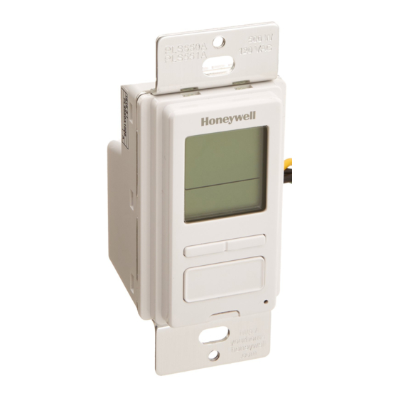
PLS550A/PLS551A
7-day Solar Programmable Wall Switch
The
icon indicates the current program
has been activated at sunset.
The
icon indicates the current program
has been activated at sunrise.
Press this button to display today's sunrise time.
Press this button to display today's sunset time.
The LED illuminates when the load state is on.
Safety switch
icon appears when the switch is in Manual mode.
icon appears when the switch is in
User guide
3.
4.
5.
1/8
Advertisement
Table of Contents

Related Manuals for Honeywell PLS550A


Summary of Contents for Honeywell PLS550A
-
Page 1: User Guide
(see shaded zone in the menu flowchart sheet). If the switch’s sunset time does not correspond to the actual sunset time, see sections 5.3.3 and 5.3.4. The PLS550A/PLS551A switch cannot be used with a load of less than 40 W or more than 500 W. ... -
Page 2: Reset To Default Settings
This warranty does not cover removal or reinstallation costs. This warranty shall not apply if it is shown by Honeywell that the defect or malfunction was caused by Set the program start time (see section 5.4.3) damage which occurred while the product was in the possession of a consumer. -
Page 3: Guide De L'utilisateur
Relier le fil « LOAD » du PLS550A/PLS551A au fil « commun » identifié lorsque vous avez enlevé l’ancien 5.1.3 Mode Aléatoire interrupteur. Relier le fils « GND » à la vis de mise à la terre dans la boîte électrique. Relier les fils « LINE »... -
Page 4: Problèmes Et Solutions
— P02 Off lundi (Mo) Si le fuseau horaire de votre ville est basé sur des frontières politiques Honeywell garantit ce produit, à l'exception des piles, contre tout vice de fabrication ou de matière P03 On aucun — P03 Off mardi (Tu) dans la mesure où... -
Page 5: Instalación
(ver el cuadro gris en el organigrama de los menús). Si la hora programada de la puesta del sol del conmutador difiere de la hora real, ver las El PLS550A/PLS551A no se puede usar con una carga inferior a 40 W o superior a 500 W. ... -
Page 6: Problemas Y Soluciones
5.3.4 Factor de corrección (ADJ) P02 On ninguno — P02 Off lunes (Mo) 22:00 Honeywell garantiza por un período de tres (3) años, a partir de la fecha de compra por el P03 On ninguno — P03 Off martes (Tu) 22:00 consumidor, que este producto, sin incluir las baterías, no presentará... -
Page 7: Menu Flowchart
PLS550A/PLS551A Menu flowchart Organigramme des menus Organigrama de los menus Flowchart shows default settings Legend / Legende / Leyenda Le diagramme contient les réglages par défaut. El diagrama contiene los ajustes por defecto. Briefly press this button to go to preceding menu or setting. - Page 8 SHREVEPORT WINDSOR JACKSONVILLE SOUTH BEND REPÚBLICA DOMINICANA WINNIPEG KANSAS CITY SPOKANE -117 Ciudad Lat. Long. Adj. KNOXVILLE YELLOWKNIFE -114 SPRINGFIELD (IL) SANTO DOMINGO LAKEWOOD -105 SPRINGFIELD (MA) PLS550A/PLS551A Printed in USA / Imprimé aux É.-U. / Impreso en EE.UU. 2010-09-29...
Need help?
Do you have a question about the PLS550A and is the answer not in the manual?
Questions and answers