Table of Contents
Advertisement
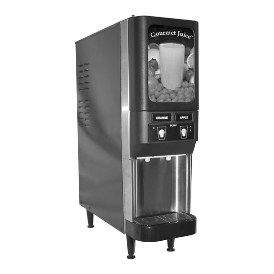
JDF-2
S/N JDF0005473 & UP
INSTALLATION & OPERATING MANUAL
BUNN-O-MATIC CORPORATION
POST OFFICE BOX 3227
SPRINGFIELD, ILLINOIS 62708-3227
PHONE: (217) 529-6601 FAX: (217) 529-6644
To obtain the Illustrated Parts Catalog, visit the Bunn-O-Matic website, at www.bunn.com. This is absolutely FREE,
and the quickest way to obtain the catalog. Contact Buun-O-Matic Corporation at 1-800-286-6070 to obtain a paper
copy of the required Illustrated Parts Catalog mailed via U.S. Postal Service.
www.bunnomatic.com
38310.0000D
01/07 ©2005 Bunn-O-Matic Corporation
Preliminary copy
Advertisement
Table of Contents

Subscribe to Our Youtube Channel
Related Manuals for Bunn JDF-2

Summary of Contents for Bunn JDF-2
- Page 1 SPRINGFIELD, ILLINOIS 62708-3227 PHONE: (217) 529-6601 FAX: (217) 529-6644 To obtain the Illustrated Parts Catalog, visit the Bunn-O-Matic website, at www.bunn.com. This is absolutely FREE, and the quickest way to obtain the catalog. Contact Buun-O-Matic Corporation at 1-800-286-6070 to obtain a paper copy of the required Illustrated Parts Catalog mailed via U.S.
-
Page 2: Table Of Contents
SOLE OPTION AS SPECIFIED HEREIN, TO REPAIR, REPLACEMENT OR REFUND. In no event shall BUNN be liable for any other damage or loss, including, but not limited to, lost profits, lost sales, loss of use of equipment, claims of Buyer’s customers, cost of capital, cost of down time, cost of substitute equipment, facilities or services, or any other special, incidental or consequential damages. -
Page 3: User Notices
USER NOTICES Carefully read and follow all notices on the equipment and in this manual. They were written for your protec- tion. All notices are to be kept in good condition. Replace any unreadable or damaged labels. 00986.0002 27442.0000 00656.0000 12559.0003 33461.0001 38310 010406... -
Page 4: Initial Set-Up & Electrical Requirements
JDF-2 is designed for indoor use only. Set the dispenser on the counter where it will be used. The JDF-2 requires a minimum of 4 inches (102 mm) of air clearance at the rear and 8 inches (203 mm) of air clearance above the dispenser. Minimal clearance is required between the dispenser sides and the wall or another appliance. - Page 5 BUNN-O-MATIC (part number 34325.10_ _ [see Illustrated Parts Catalog for complete part number.]) BUNN-O-MATIC does not recommend the use of saddle valves to install the dispenser. The size and shape of the hole(s) made in the supply line(s) by saddle valves may restrict water flow.
- Page 6 “out of brix” drink. Ambient Concentrates (Optional) 1. Install an Ambient Concentrate Conversion Kit (BUNN-O-MATIC part number 33699.0001) per the instruc- tions provided in the kit. 2. Attach the concentrate product hose to the appropriate concentrate line located at the rear of the dispens- 3.
-
Page 7: Operating Controls
OPERATING CONTROLS Refrigeration Switch The refrigeration switch is located on the top of the dispenser near the left rear corner. This switch controls power to the compressor and the condenser fan motor. P2261 FIG 3 Refrigeration Switch Sanitize Switch The sanitize switch is located behind the drip tray in the lower left corner of the chassis. - Page 8 OPERATING CONTROLS (cont.) FIG 5 Press and Hold Models A. Product Dispense Switch Pressing and holding switch will initiate product flow from the respective nozzle; releasing the switch will stop the flow. B. Hidden Switch These switches are used to access, change and exit the dispenser program mode. C.
-
Page 9: Dispenser Use
DISPENSER USE Press and Hold Models (Refer to Fig 5) 1. Place a cup on the drip tray beneath the desired dispensing nozzle. 2. Press and hold the “Product Dispense” switch until the beverage reaches the desired level, then release. Portion Control Models (Refer to Fig 6) 1. - Page 10 3. Close the refrigerated compartment’s door. 4. Place the empty container under the dispense nozzle to catch the rinse water. (CAUTION: THE BUNN JUICE DISPENSER CAN BE PLUMBED FOR A HOT WATER RINSE. RINSE WATER CAUGHT IN THIS STEP SHOULD BE HANDLED WITH EXTREME CARE.) 5.
-
Page 11: Cleaning
CLEANING (cont) 6. Select the dispense stations by pressing the “Dispense Switch” for that station. Use the “+/Stop Switch” for portion contol dispensers. The “REFILL” indicator will light and the beeper will sound for the dispense head selected. 7. Once the dispense heads have been selected, press and hold the “Sanitize Switch” for 5 seconds again to initiate the automatic cycle. - Page 12 CLEANING (cont) Monthly: Clean Condenser Air Filter 1. Remove the condenser air filter located on the rear of the dispenser. 2. Using a water spray, clean the air filter. Annually: Replace Pump Tubing 39689.0000 Tube Kit JDF-2S & JDF-4S 39687.0000 Tube Assembly NOTE: High volume applications may require tubing changes every 6 months.
-
Page 13: Adjustments & Optional Settings
ADJUSTMENT & OPTIONAL SETTINGS Total Dispense Ratio Set Up Procedure 1. Adjust water flow as described in Water Flow Testing and Adjustment. Record water output setting for later reference on each dispense head. 2. Enter program mode by simultaneously pressing both hidden switches. 3. - Page 14 “PROGRAM” indicator begins flashing. 2. Place a graduated measuring cup or the large chamber of the empty brixing cup (BUNN-O-MATIC part number 33095.0000) under the ap- propriate dispense nozzle. 3. Press and hold the desired “Product Dispense Switch” Fig 5 (“+/Stop Switch”...
- Page 15 ADJUSTMENT & OPTIONAL SETTINGS (cont) Pump Speed Programming 1. Enter the “Pump Speed Programming” mode by simultaneously pressing both “Hidden Switches”. Note that the beeper sounds twice and that the “PROGRAM” indicator begins flashing. 2. To increase the pump speed, press and hold the right-hand “Hidden Switch” (filled circle) and then momen- tarily press the “Product Dispense Switch”...
- Page 16 ADJUSTMENT & OPTIONAL SETTINGS (cont) Dispenser Lockout Dispense and Rinse functions of the dispenser can be electronically locked-out to prevent unauthorized use of the dispenser, while keeping the refrigeration system running. 1. Enter the “Pump Speed Programming” mode by simultaneously pressing both “Hidden Switches”. Note that the beeper sounds twice and that the “PROGRAM”...
- Page 17 ADJUSTMENT & OPTIONAL SETTINGS (cont) 3. To remove a dispense station from “Service Lockout,” press and hold either “Hidden Switch” and the desired dispense station “Product Dispense” (“+/Stop”) switch for 10 seconds. 4. At the end of the 10 second period, the beeper will sound a double tone and the dispense position will be enabled.
- Page 18 Dispense Fault List “REFILL” indicator Beeper Fault 2 flashes 2 beeps Dispense station locked out. 3 flashes 3 beeps DISPENSE/RINSE sensing fault. 4 flashes 4 beeps DISPENSE/RINSE knob mis-positioned. 5 flashes 5 beeps Pump motor stalled/speed sensor inoperative. All “REFILL” 3 beeps Dispenser locked out.
- Page 19 Dip Switch Function List Dip Switch Controls “REFILL” indicator when “concentrate out” is detected. Inactive Active Lockout dispense components when “concentrate out” is detected. Inactive Active (Note) Number of positions that can dispense/rinse simultaneously. Rinse timer Audio feedback during dispenses. Future use.
-
Page 20: Function Lists
FUNCTION LIST Function # Description Default Setting Enter Password Set Pump 1 RPM (Concentrate A) Set Pump 2 RPM (Concentrate A) Set Pump 3 RPM (Concentrate A) Set Pump 4 RPM (Concentrate A) Set Pump 1 RPM (Concentrate B) Set Pump 2 RPM (Concentrate B) Set Pump 3 RPM (Concentrate B) Set Pump 4 RPM (Concentrate B) Station 1 Large Cup Dispense Time (seconds) -
Page 21: Troubleshooting
TROUBLESHOOTING A troubleshooting guide is provided to suggest probable causes and remedies for the most likely problems encountered. If the problem remains after exhausting the troubleshooting steps, contact the Bunn-O-Matic Technical Service Department. • Inspection, testing, and repair of electrical equipment should be performed only by qualified service person- nel. - Page 22 TROUBLESHOOTING (cont.) PROBLEM REMEDY PROBABLE CAUSE Refrigeration 1. Compressor ON/OFF switch. Check for "ON" position or no con- tinuity - replace switch. All dispense stations not working or all water & refill LED's flash and 2. Dirty condenser filter or fins. Clean or replace condenser filter.
- Page 23 TROUBLESHOOTING (cont.) PROBLEM REMEDY PROBABLE CAUSE Dispense station not working "refill" 1. Bottle adapter switch mem- Check for moisture at 3-pin con- LED and beep code. brane nector and clean. Apply electrical insulating compound or replace A) 3-Beep - Dispense/Rinse sens- A) Dispense/Rinse switch mem- defective switch membrane.
- Page 24 TROUBLESHOOTING (cont.) PROBLEM REMEDY PROBABLE CAUSE Dispense station Water solenoid Replace solenoid (24vdc) or check concentrate only wire connection between water valve and main control board. Dispense station In rinse position Rotate knob to dispense position. water only NOTE": Water will dispense for 4 seconds.
- Page 25 TROUBLESHOOTING (cont.) PROBLEM REMEDY PROBABLE CAUSE Water leak filling drip tray or around 1. Initial fill/setup Some expansion normal. May fill dispense deck area drip tray during initial ice block formation 2. Dispense deck Inspect or replace fittings clamps, o-rings, solenoids and quick discon- nect fittings.
- Page 26 TROUBLESHOOTING (cont.) PROBLEM REMEDY PROBABLE CAUSE Unit is not working and no beep/light 1. Step-down transformer. Check for 120/24 vac. If no 24vac fault codes reading, replace step-down trans- former. 2. Main control board. If 24 vac present and no red LED, replace control board..
- Page 27 TROUBLESHOOTING (cont.) PROBLEM REMEDY PROBABLE CAUSE Difficulty brixing and/or weak bev- 1. Pump tubing. Inspect, clean, or replace tubing erage and pump rotor/rollers for ease of rotation. 2. Bottle adapter assembly leaking Replace bottle adapter assembly. NOTE: Leaking water into con- centrate bottle during rinse of any station.
-
Page 28: Coolant Diagram
COOLANT SCHEMATIC DIAGRAM 38310 010406... -
Page 29: Schematic Wiring Diagram
SCHEMATIC WIRING DIAGRAM SCHEMATIC WIRING DIAGRAM JDF-2 120V 230V MODELS MODELS OPTIONAL FLUORESCENT WHI/GRN LAMP BALLAST ON/OFF BLU/BLK BRN/BLK LAMP ASSY. TRANSFORMER CONDENSOR FAN BLU/BLK WHI/BLU FILTER MOTOR – COMPRESSOR ASSEMBLY RECT LIMIT WHI/GRY RINSE THERMOSTAT BLU/BLK RED/BLK COMP. RED/BLK... - Page 30 24 VDC INPUT, J6-12 0/5 VDC SWITCHING OUTPUT J3-1 J3-2 J1-1 J8-8 WHI/ORN J7-1 J1-5 SCHEMATIC WIRING DIAGRAM WHI/ORN J7-5 JDF-2 DISPENSE DECK CIRCUIT J1-10 J7-10 WHT/VIO WHI/VIO J1-18 J7-16 #1 REFILL #2 REFILL SENSOR SENSOR #1 RINSE & #2 RINSE &...
- Page 31 BLU/WHI BLK/WHI J7-5 J1-10 RED/WHI J7-10 BLU/BLK GRN/BLK ORN/BLK WHI/BLK J1-18 J7-16 SCHEMATIC WIRING DIAGRAM JDF-2 CONTROL PANEL CIRCUIT To Switch Unit Assembly SWITCH UNIT ASSEMBLY (Push Button Control models) SHIELD SWITCH UNIT ASSEMBLY (Portion Control Models) SHEILD 38310 010406...
- Page 32 120 VAC or – COMPRESSOR ASSEMBLY 230 VAC RECT WHI/GRY LIMIT RINSE THERMOSTAT 24 VDC BLU/BLK RED/BLK COMP. RED/BLK SCHEMATIC WIRING DIAGRAM JDF-2 REMAINING CIRCUITS SANITIZE SWITCH J6-1 24 VDC WHI/BLU J11-1 5 VDC WHI/VIO WATER J11-3 INLET J9-1 J6-6 RED/BLK...
Need help?
Do you have a question about the JDF-2 and is the answer not in the manual?
Questions and answers