Table of Contents
Advertisement
Available languages
Available languages
Installer: Leave this manual with the appli-
ance.
Consumer: Retain this manual for future refer-
ence.
This appliance may be installed in an after-
market, permanently located, manufactured
home (USA only) or mobile home, where not
prohibited by state or local codes.
This appliance is only for use with the type of gas
indicated on the rating plate. This appliance is
not convertible for use with other gases, unless
a certified kit is used.
WARNING: If not installed, operated and
maintained in accordance with the manufactur-
er's instructions, this product could expose you
to substances in fuel or from fuel combustion
which can cause death or serious illness.
INSTALLATION INSTRUCTIONS
OWNER'S MANUAL
AND
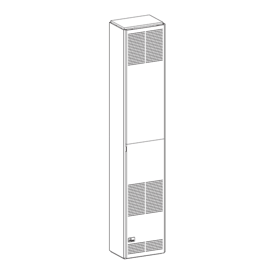
FAN TYPE
DIRECT VENT
WALL FURNACE
MODEL
DV-55IP
WARNING: If the information in these instruc-
tions are not followed exactly, a fire or explosion
may result causing property damage, personal
injury or loss of life.
— Do not store or use gasoline or other flamma-
ble vapors and liquids in the vicinity of this or
any other appliance.
— WHAT TO DO IF YOU SMELL GAS
•
Do not try to light any appliance.
•
Do not touch any electrical switch; do not
use any phone in your building.
•
Immediately call your gas supplier from a
neighbor's phone. Follow the gas suppli-
er's instructions.
•
If you cannot reach your gas supplier, call
the fire department.
— Installation and service must be performed by
a qualified installer, service agency or the gas
supplier.
Page 1
Advertisement
Table of Contents

Subscribe to Our Youtube Channel
Related Manuals for Empire DV-55IP


Summary of Contents for Empire DV-55IP
-
Page 1: Installation Instructions
OWNER'S MANUAL FAN TYPE DIRECT VENT WALL FURNACE MODEL DV-55IP Installer: Leave this manual with the appli- WARNING: If the information in these instruc- ance. tions are not followed exactly, a fire or explosion Consumer: Retain this manual for future refer- may result causing property damage, personal ence. -
Page 2: Table Of Contents
TABLE OF CONTENTS SECTION PAGE Important Safety Information ........................3 Safety Information for Users of LP Gas ......................4 Requirements for Massachusetts ........................5 Introduction ..............................6 Specifications ...............................6 Gas Supply ............................... 7-8 Clearances ..............................8 Installation Instructions .......................... 9-11 Lighting Instructions ..........................12 Pilot Flame Characteristics ........................13 Main Burner Flame Characteristics ......................13 Wiring ................................14 Service and Maintenance Suggestions .................... -
Page 3: Important Safety Information
IMPORTANT SAFETY INFORMATION THIS IS a HeaTING aPPLIaNCe DO NOT OPeRaTe THIS aPPLIaNCe WITHOUT FRONT PaNeL INSTaLLeD. • Due to high temperatures the appliance should be located excessive lint from carpeting, bedding materials, etc. It is out of traffic and away from furniture and draperies. imperative that control compartments, burners and circu- lating air passageways of the appliance be kept clean. -
Page 4: Safety Information For Users Of Lp Gas
SAFETY INFORMATION FOR USERS OF LP-GAS Propane (LP-Gas) is a flammable gas which can cause fires by point with the members of your household. Someday when and explosions. In its natural state, propane is odorless and there may not be a minute to lose, everyone's safety will depend colorless. -
Page 5: Requirements For Massachusetts
REqUIREMENTS FOR MASSACHUSETTS For all side wall horizontally vented gas fueled equipment 3. SIGNAGE. A metal or plastic identification plate shall be installed in every dwelling, building or structure used in permanently mounted to the exterior of the building at a whole or in part for residential purposes, including those minimum height of eight (8) feet above grade directly in owned or operated by the Commonwealth and where the... -
Page 6: Introduction
3.5" w.c. (.871kPa) to 2.8" w.c. (.697kPa) for Natural Gas and from depth of the appliance. 10.0" w.c. (2.49kPa) to 8.0" w.c. (1.992kPa) for Propane Gas. SPECIFICATIONS Model DV-55IP Input BTU/HR 55,000 Height 82 3/8" Width 16"... -
Page 7: Gas Supply
GAS SUPPLY Locating Gas Supply a manual main gas cock should be located in the vicinity of The gas line can enter the unit either through the floor or outside the unit. Where none exists, or where its size or location is not wall. -
Page 8: Clearances
Checking Manifold Pressure Both Propane and Natural gas valves have a built-in pressure regulator in the gas valve. Natural gas models will have a mani- fold pressure of approximately 3.5" w.c. at the valve outlet with the inlet pressure to the valve from a minimum of 5.0" w.c. for the purpose of input adjustment to a maximum of 7.0"... -
Page 9: Installation Instructions
INSTALLATION INSTRUCTIONS Locating Wall Opening The furnace is to be located on an outside wall. Locate wall studs so that wall opening will be located between wall studs. The furnace is 16 inches in width and normal 16 inches on center studs will not allow the furnace to be recessed into the wall unless a stud is repositioned. - Page 10 1. attach 6" diameter air inlet tube onto the collar of air drop assembly. Be sure 6" diameter air inlet tube is placed as far as possible onto the collar of the air drop assembly. Mark the 6" diameter air inlet tube 1/2" beyond the outside wall. Remove 6"...
-
Page 11: Installation Instructions
2" x 4" framing should not exceed a total depth of 13" for DV-55. (See Figure 9) Vinyl siding vent kit, DV-822, is available from empire Comfort Systems, Inc. The depth is 3", which enables the vent cap to be extended away from siding or projections. -
Page 12: Lighting Instructions
LIGHTING INSTRUCTIONS FOR YOUR SAFETY READ BEFORE OPERATING WARNING: If you do not follow these instructions exactly, a fire or explosion may result causing property damage, personal injury or loss of life. A. This appliance is equipped with an ignition device which •... -
Page 13: Pilot Flame Characteristics
PILOT FLAME CHARACTERISTICS The pilot flame (Figure 11) going to the spark must be large enough to completely cover the sparking area. With the proper flame, only 2 or 3 sparks will occur. More sparks indicate a small pilot flame and no ignition with spark stopping after approximately 90 seconds generally means not enough flame. -
Page 14: Wiring
WIRING Wiring The appliance, when installed, must be electrically grounded in accordance with local codes or, in the absence of local codes, with the National Electrical Code, ANSI/NFPA 70 or Canadian Electrical Code, CSA C22.1, if an external electrical source is utilized. This appliance is equipped with a three-prong [grounding] plug for your protection against shock hazard and should be plugged directly into a properly grounded three-prong receptacle. -
Page 15: Service And Maintenance Suggestions
GaS LeaK TeST: Paint pipe joints with rich soap and water solution. Bubbles indicate gas leak. Tighten joints to stop leak. The Service Department at empire Comfort Systems, Inc. may be contacted to assist in servicing furnace or call a qualified serviceman. - Page 16 TRIAL FOR IGNITION The control system must be reset by setting the thermostat below room Pilot Ignition temperature for one minute or by turning off power to the module for Following call for heat (system start on S8600H), the module energizes the one minute.
-
Page 17: Troubleshooting
TROUBLESHOOTING Important WaRNING 1. The following service procedures are provided as a general When performing the following steps, do not touch stripped end guide. of jumper or SPaRK terminal. The ignition circuit generates 2. Meter readings between gas control and ignition module must 13,000 volts at 25 pf load and electrical shock can result. - Page 18 TROUBLESHOOTING Page 18 12432-13-1008...
- Page 19 TROUBLESHOOTING Green LED Status Codes Green LED Flash Code (X + Y) Indicates Next System Action Recommended Service Action No “Call for Heat” Not applicable None Flash Fast Startup-Flame sense calibration Not applicable None Heart Beat Normal operation Not applicable None Recycle Initiate new trial for ignition.
-
Page 20: How To Order Repair Parts
Do not order bolts, screws, washers or nuts. They are standard hardware items and can be purchased at any local hardware store. Shipments contingent upon strikes, fires and all causes beyond our control. Page 20 12432-13-1008 Empire Comfort Systems, Inc. Nine eighteen Freeburg ave. Belleville, IL 62222-0529... -
Page 21: Parts View
PARTS VIEW 12432-13-1008 Page 21... -
Page 22: Service Notes
SERVICE NOTES Page 22 12432-13-1008... - Page 23 SERVICE NOTES 12432-13-1008 Page 23...
- Page 24 Comfort Systems Inc. EMPIRE EMPIRE 918 Freeburg ave. Belleville, IL 62220 If you have a general question about our products, please e-mail us at info@empirecomfort.com. If you have a service or repair question, please contact your dealer. Comfort Systems www.empirecomfort.com...
- Page 25 MANUEL DU PROPRIéTAIRE RADIATEUR MURAL à CIRCULATION FORCéE AVEC UN éVENT DIRECT MODèLES DV-55IP AVERTISSEMENT: Assurez vous de bien suivre les instructions données dans cette notice pour réduire au minimum le risque d’incendie ou Installateur: Laissez cette notice avec l’appareil.
- Page 26 Spécifications National Standard / CSA Standard Z21.86 et CSA 2.32 par Canadian Standards Association comme étant un radiateur mural Modèle DV-55IP à circulation forcée avec un évent direct, devant être installé en Puissance KW/H 55,000 (161.12) accordance avec ces instructions.
- Page 27 INFORMATION DE SéCURITé POUR LES UTILISATEURS DE PROPANE Le propane est un gaz inflammable qui peut causer des feux et des n’y aura pas une minute à perdre, la sécurité de chacun dépendra de explosions. Dans son état naturel, le propane est inodore et sans couleur. votre savoir-faire.
- Page 28 Agence d’Installation Qualifiée 16" (40.64cm) le radiateur pourra être encastré seulement si un L’installation et le remplacement des tuyaux à gaz, des équipe- montant est changé de place. Comme le représente la Figure 2, ments ou accessoires, la réparation et l'entretien de l'équipement l’ouverture dans le mur exige un diamètre de 7 1/2"...
- Page 29 MINIMUM 4” (10.16CM) MINIMUM 4” (10.16CM) AUX MATÉRIAUX AUX MATÉRIAUX COMBUSTIBLES COMBUSTIBLES GUIDE VUE GUIDE VUE DE DESSUS DE DESSUS CAPUCHON D’ÉVENT PAS SI REGISTRES GUIDE REPRESENTÉ DE CÔTÉ NE (IDENTIQUE Á SONT PAS L’AUTRE CÔTÉ) UTILISÉS MINIMUM DE 18” (45.7CM) AUX APPAREIL PEUT APPAREIL NE PEUT PAS ÉTRE ENCASTRÉ...
- Page 30 2. Attacher le tuyau d’échappement de 4" (10.16cm) de diamètre Emplacement de l'Alimentation électrique sur le collet de la sortie d’échappement qui est sur la chambre Sur le bas des panneaux des côtés gauche et droit, il y a une entrée de combustion.
- Page 31 être fait. L’ensemble d’évent pour le revêtement en vinyle, DV-822, est disponible chez Empire Comfort Systems, Inc. L’épaisseur est de Ne jamais employer une flamme pour vérifier les fuites. Lors d’un 3" (7.62cm) ce qui permet le prolongement du capuchon d’évent test de pression, le tuyau d’arrivée de la valve de commande doit...
- Page 32 Aspect Convenable de la Flamme de la Veilleuse Méthode pour installer un collecteur de sédiment avec un adapteur en T La flamme de la veilleuse (Figure 8) allant à l'étincelle doit être assez grande pour couvrir complètement la zone d'étincelle. Seulement L’emploi des connexions de gaz suivantes est recommandé: 2 ou 3 étincelles apparaîtront lorsque la flamme sera convenable.
- Page 33 Figure 9 Remplacement du Ventilateur et Huilage du Moteur Le moteur du ventilateur doit être nettoyé et huilé une fois chaque saison de chauffage. Pour atteindre le moteur, enlever le blindage métallique autour des ailettes du ventilateur en enlevant les vis de chaque côtés.
- Page 34 POUR VOTRE SéCURITé LIRE AVANT D’ALLUMER AVERTISSEMENT: Si vous ne suivez pas exactement ces instructions, un feu ou une explosion peut se produire causant des dommages à la propriété, des blessures corporelles ou la mort. A. Cet appareil est muni d'un dispositif d'allumage lequel allume instructions du fournisseur de gaz.
- Page 35 Pour vous assister à l’entretien du radiateur, vous pouvez contacter le éTAPE 2: Réviser les séquences de manoeuvres normales et les département de service à Empire Comfort Systems, Inc. spécifications du module. Entretien de la veilleuse et des brûleurs principaux, de l'ouverture de la éTAPE 3: Remettre à...
- Page 36 de 25pf). La tension produit une étincelle au détecteur d’allumage lequel Fonctionnement du Brûleur Principal allume la veilleuse. Lorsque la flamme de la veilleuse est bien établie, un circuit de redresse- ment de la flamme est complété entre le détecteur et le fond du brûleur. Si la veilleuse ne s’allume pas ou si le courant de la flamme de la veilleuse Le circuit de détection de la flamme dans le module détecte le courant n’est pas d’au moins 1.0 uA et constante, le module n’alimentera pas la...
- Page 37 DéTECTION DES DéFECTUOSITéS Important AVERTISSEMENT 1. Les procédures d’entretien suivantes sont fournies comme étant Lorsque vous exécutez les étapes suivantes, ne toucher pas à un guide général. l’extrémité dénudée du pont ou de la borne d’étincelle. Le circuit 2. Les lectures de compteu d’allumage produit un courant électrique de 13,000 volts à...
- Page 38 DÉP ART Note: A vant de détecter les défectuosités, familiarisez-vous avec la mise en marche et les procédures de vérification Fermer l'alimentation de gaz. Régler le thermostat our un appel de chaleur Vérifier le pouvoir de la ligne de tension, le transformateur à basse ten- Pouvoir du module sion, le contrôle de tolérance, le thermostat et l'installation électrique.
- Page 39 S’IL VOUS PLAîT NOTER: Lorsque vous commandez les pièces, il est très important que le numéro de la pièce et la description coïncident. Numéro Numéro Numéro Numéro d’index de la pièce d’index de la pièce Description Description 11762 Dessus de la paroi extérieure DV-781 Assemblage du couvercle de 632024...
- Page 40 Empire Comfort Systems Inc. EMPIRE EMPIRE 918 Freeburg Ave. belleville, IL 62220 Pour toute question générale concernant nos produits, veuillez nous envoyer un courriel à info@empirecomfort.com. Pour toute question d’entretien ou de réparation, veuillez contacter votre revendeur. Comfort Systems www.empirecomfort.com...
Need help?
Do you have a question about the DV-55IP and is the answer not in the manual?
Questions and answers