Advertisement
Advertisement
Table of Contents

Related Manuals for Harman Kardon Car Stereo System
![Car Stereo System HARMAN KARDON DRIVE + PLAY [HK-DP1EU] Owner's Manual](https://static-data2.manualslib.com/product-images/35a/642606/60x60/harman-kardon-drive-play-hk-dp1eu-car-stereo-system.jpg)
Summary of Contents for Harman Kardon Car Stereo System
- Page 1 Owner’s Manual...
-
Page 2: Ipod Software
INTRODUCTION Thank you for purchasing Harman Kardon’s Drive + Play™, an elegant mobile audio solution that provides the driver with total iPod ® control, including full music browsing capability. We’ve organized this manual to make installation and operation as simple and trouble-free as possible. Please read it thoroughly before you begin installing Drive + Play. -
Page 3: Installation
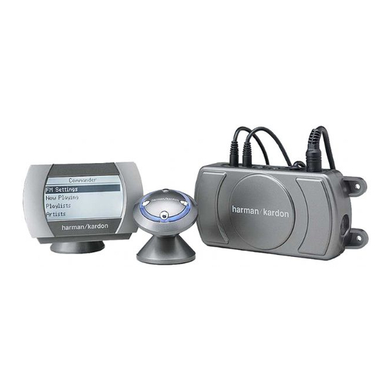
INSTALLATION Parts List Drive + Play includes the following components and parts: • Text Display With Universal Mounting Base and Attached Cable (3m) • Control Knob With 30° Mounting Base and Attached Cable (3m) • Electronics Enclosure (the Brain) • 12-Volt Accessory Power Cable (2m) With Cigarette Lighter Adaptor •... - Page 4 Choosing Installation Locations (continued) Electronics Enclosure Location The Electronics Enclosure contains the wireless FM transmitter and the power supply for the three components. You can install it under a seat, in the center console compartment, or in the glove box. If possible, select a site that provides both conven- ient access to the enclosure and easy cable routing.
-
Page 5: Wiring Diagram
Wiring Diagram iPod iPod Cable Electronics Enclosure Side Back 12-Volt Power 3.5mm Stereo Cable Harness (not included) 2A Fuse Auxiliary Device (optional) +12Vdc = yellow ACC = red Cell Phone, Satellite Radio, etc. GND = black Direct Connection of the 12-Volt Power Harness With In-Line Fuse Holder Use this method when you want a permanent power connec- tion to the vehicle. -
Page 6: Installing Components
Installing Components Installing the Electronics Enclosure At the selected site, install the Electronics Enclosure. Use either the enclosed cable ties or mounting screws, as shown below. Installing the Text Display 1. Temporarily place the Text Display at the proposed site and check the default viewing angle while adjusting the pivot arm. - Page 7 b. At the proposed site, wipe the surface and exposed mounting plate with one of the enclosed alcohol pads. Allow both to dry. c. Remove the protective tape from one side of one of the enclosed adhesive pads, and press the pad against the mounting plate.
-
Page 8: Operating
Installing Components Installing the Control Knob (continued) 2. At the base (below the cable), using the 1.5mm hex key, loosen (but do not remove) the hex setscrew. 3. To install the Control Knob with adhesive tape, perform the following steps or skip to step 4: a. -
Page 9: Operation
Drive + Play operates much like the iPod itself. The Control Knob mimics the iPod’s Click Wheel, and its software uses a similar menu-select system. Before you use Drive + Play, you’ll need to set it up for the first time. After you perform the Initial Setup using the Settings Menu, controlling your iPod with Drive + Play will be easy and intuitive. - Page 10 Initial Setup (continued) Setting AUX Input To route an audio signal from a device (e.g., cell phone or satellite radio; see Wiring Diagram on page 5) connected to Drive + Play’s auxiliary input to your mobile audio system: • To enable or disable automatic sensing and switching of audio signals on Drive + Play’s auxiliary input: Drive + Play Menu >...
- Page 11 Setting the Sleep Timer Drive + Play is equipped with a sleep timer that delays its power off by a default of 2 seconds after the ignition is turned off. You can set a different delay time as follows: NOTE: Sleep Timer only works when the Drive + Play’s ACC wire is connected to the ignition switch’s accessory terminal (see Wiring Diagram on page 5).
-
Page 12: Troubleshooting
TROUBLESHOOTING Problem: Message = iPod Disconnected Solution: • Check that the iPod Connection Cable is connected between the Electronics Enclosure and the iPod. Problem: Message = AUX is Disabled Solution: • Check AUX Input (see page 10). • Check the connection between the Electronics Enclosure and the auxiliary device.
Need help?
Do you have a question about the Car Stereo System and is the answer not in the manual?
Questions and answers