Table of Contents
Advertisement
Quick Links
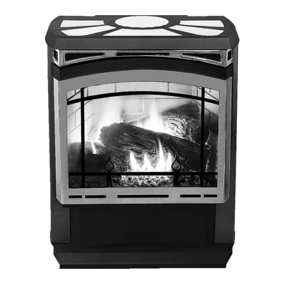
The Harman Conquest Gas Stove
PLEASE READ THIS ENTIRE MANUAL BEFORE YOU INSTALL AND USE YOUR NEW ROOM HEATER. FAILURE TO
FOLLOW INSTRUCTIONS MAY RESULT IN PROPERTY DAMAGE, BODILY INJURY, OR EVEN DEATH.
FOR USE IN THE U.S. AND CANADA. SUITABLE FOR INSTALLATION IN MOBILE HOMES
IF THIS HARMAN STOVE IS NOT PROPERLY INSTALLED, A HOUSE FIRE MA Y RESULT. FOR YOUR SAFETY, FOLLOW
INSTALLATION DIRECTIONS.
CONTACT LOCAL BUILDING OR FIRE OFFICIALS ABOUT RESTRICTIONS AND INSTALLATION INSPECTION
REQUIREMENTS IN YOUR AREA.
CONTACT YOUR LOCAL AUTHORITY (SUCH AS MUNICIPAL BUILDING DEPARTMENT, FIRE DEPARTMENT, FIRE
PREVENTION BUREAU, ETC.) TO DETERMINE THE NEED FOR A PERMIT.
CETTE GUIDE D'UTILISATION EST DISPONIBLE EN FRANCAIS. CHEZ VOTRE CONCESSIONNAIRE DE HARMAN ST OVE
COMPANY.
Installation & Operating Manual
"Ce manuel est disponible en Français sur demande"
SAFETY NOTICE
SAVE THESE INSTRUCTIONS.
1
R6
A
B
C
R1
Advertisement
Table of Contents
Troubleshooting

Related Manuals for Harman Stove Company Conquest Gas Stove


Summary of Contents for Harman Stove Company Conquest Gas Stove
-
Page 1: Safety Notice
FOLLOW INSTRUCTIONS MAY RESULT IN PROPERTY DAMAGE, BODILY INJURY, OR EVEN DEATH. FOR USE IN THE U.S. AND CANADA. SUITABLE FOR INSTALLATION IN MOBILE HOMES IF THIS HARMAN STOVE IS NOT PROPERLY INSTALLED, A HOUSE FIRE MA Y RESULT. FOR YOUR SAFETY, FOLLOW INSTALLATION DIRECTIONS. -
Page 2: For Your Safety
This appliance must be installed in accordance with local codes, if any, if not; follow the current edition of the National Fuel Gas Code, ANSI Z223.1 or Canadian Installation Codes, CAN/CGA B149. (Installer l’appareil selon les codes ou règlements locaux, ou, en l’absence de tels règlements, selon les Codes d’installation CAN/ CGA-B149) CAUTION: Do not operate the appliance with glass removed, cracked or broken. -
Page 3: Table Of Contents
Table of Contents Introduction Safety Precautions Operation Specifications Clearances Installation Venting Changing To Natural Gas Option Installation Thermostat Remote Control Glass Grill Blower Maintainence Wiring Diagram Parts Trouble Shooting Manufactured by The Harman Stove Company 352 Mountain House Rd. Halifax PA 17032... -
Page 4: Introduction
Several issues must be addressed when select- ing a suitable location for your Conquest Gas Stove. Observing required clearances to combustible ma- terials, the proximity to a safe chimney or venting system location, and the accessibility of the gas and electrical supply must all be considered. -
Page 5: Operation
OPERATION Operation HOW TO LIGHT THE FIRE 1. STOP! Read the safety information on the front cover of this manual. 2. If using the optional thermostat, set thermostat to the lowest setting. 3. Turn off electric power to the optional blower. 4. -
Page 6: How To Turn Off The Fire
2. Turn off the electric power to the blower. 3. Turn the ON-OFF switch on the upper right rear of the stove to the OFF position. 4. Push in the gas control knob slightly and turn it clockwise to “OFF.”... -
Page 7: Specifications
RATINGS Input Rating (Btu/hr)(0-4500 ft.)(0-1375 m) Min. Input Rating (Btu/hr)(0-4500 ft.)(0-1375 m) Orifices (DMS)(0-4500 ft.)(0-1375 m) Manifold Pressure (in w.c./kPa) Min. Manifold Pressure (in w.c./kPa) Min. Inlet Pressure (in w.c./kPa) Max. Output (Btu/hr)(0-4500 ft.)(0-1375 m) (Blower Off) SPECIFICATIONS NATURAL 29000 14900 3.8/.95 1.1/.27... -
Page 8: Clearances
MINIMUM CLEARANCES FROM COMBUSTIBLE CONSTRUCTION Unit to corner walls Unit to side wall Unit to back wall Unit to alcove ceiling Maximum alcove depth Electrical Rating: 120 Volts, 60 Hz, > 3” Side And Back Wall Clearances 8” SPECIFICATIONS 2 in. 8 in. -
Page 9: Installation
Making The Connection The gas inlet is located on the bottom right side of the stove. The inlet fitting is a 1/2" male flare fitting. A separate gas shut-off valve and a 1/8" N.P.T. - Page 10 Consult your local building codes before beginning the installation, and follow the manufacturer's instructions exactly. The Simpson Duravent GS venting components listed below are approved for use with the Conquest Direct Vent Gas Stove. Part Numbers for SimpsonDura-Vent Pipe and Fittings 8”...
-
Page 11: Venting
Only For Qualified Installers This appliance must not be connected to a chimney flue serving a separate solid fuel burning appliance. Vent termination must remain within the shaded area regardless of configuration. INSTALLATION CONQUEST ” x 4” Pipe Venting with 6 Maximum of four 45 elbows allowed. - Page 12 Only For Qualified Installers Requirements for Terminating the Venting WARNING: Venting terminals must not be re- cessed into a wall or siding. In addition, the following must be observed: A. The clearance above grade, or a veranda, porch, deck or balcony must be a minimum of 12" (30 cm).
- Page 13 Only For Qualified Installers A vent damper is provided to allow fine tuning of the draft. Too little draft will cause flames to be too long with black tips and too much draft will cause flames to be short and blue. To adjust the damper, burn the unit on High 10 minutes or more.
-
Page 14: Changing To Natural Gas
Remove four bolts and remove burner module from stove. Natural Gas Kit This kit is only for use in the Conquest direct vent gas stove. NG Pilot Orifice NG Orifice #37 NG Conversion label NG Valve Conversion Module NG Conversion Instructions Part No. - Page 15 Only For Qualified Installers Reinstall burner module back into the stove with the four bolts that were removed. Check gasket for damage and replace if necessary. Check for gas leaks when finished. INSTALLATION Note: The higher the orifice number the smaller hole in the tip.
-
Page 16: Ember Placement
Only For Qualified Installers Rear Log Front Log Andirons Air Deflector Place the front log as shown between the andirons and the air deflector. INSTALLATION Log Placement Place the rear log behind the front log with the branch resting on the front log on the right side as shown. Before lighting a fire check that the rear log is as far back against the rear wall as possible. - Page 17 Only For Qualified Installers Round Tile Not Used On Top Vent INSTALLATION Tile Kit Each tile kit contains six tiles and fifteen allen- set screws. If the Conquest is installed as a top vent, then the round tile is not used. If it is installed as a rear vent, then the trim ring is not used.
-
Page 18: Thermostat
Only For Qualified Installers Thermostat Burner Button Glass Grill INSTALLATION (Options) Connecting the Optional Thermostat If the optional thermostat is used, it must be plugged into the TH terminals located on the valve. When installing a millivolt control system, use only a special low resistance thermostat. -
Page 19: Optional Blower
A special switch is used to automatically start the blower when the stove temperature is hot enough to blow warm air. This switch will also stop the blower when the stove temperature drops below the point that warm air is available. -
Page 20: Maintenance
If the glass door or side doors are removed for servicing, they must be replaced prior to operating the stove. Latch Air Grill CAUTION: Do not operate this appliance with the glass front removed, cracked, or broken. - Page 21 Air Out Air Out Air In The flow of combustion and ventilation air must not be obstructed. The appliance should be inspected before use and at least annually by a qualified service person. More frequent cleaning may be required due to excessive lint from carpeting, bedding material, etc.
-
Page 22: Wiring Diagram
Optional Blower Wiring Diagram ( 120 Volt ) Temperature Switch Blower Power Cord “Caution: Label all wires prior to disconnection when servicing controls. Wiring errors can cause improper and dangerous operation. Verify proper operation after servicing”. MAINTENANCE Low Voltage Wiring Diagram Speed Control Valve... -
Page 24: Parts
1) 1-89-09100 Body weldment 2) 1-10-09100 LP valve assembly 3) 1-00-09102 Optional blower 4) 1-00-09105 Optional window grid 5) 1-10-73102 Pedestal weldment 6) 3-43-09100 Gold door frame 7) 1-10-09108 Door weldment 8) 3-40-09102 Door glass Glass gasket (7’/unit) 9) 3-44-00539 10) 3-44-08294 Flue gaskets 11) 3-43-09110... -
Page 25: Burner Parts
1) 3-40-08715 LP pilot 2) 2-00-73122 Igniter mount 3) 3-40-08220 Igniter (piezo) 4) 3-31-09100 90 degree street elbow 5) 3-40-09106 50% turn down LP valve 1/2” flare fitting 6) 3-31-08792 7) 3-44-73174 Valve gasket 8) 3-90-4273 Gas label 9) 2-00-73125 Sealer plate MAINTENANCE Burner Parts... -
Page 26: Trouble Shooting
Is gas turned "on"? Is there gas in tank (LP) or line (NG) Purge gas line to stove Check pilot orifice and pilot line for blockage. TROUBLE SHOOTING Pilot does not light after many tries. -
Page 27: Trouble Shooting
Only For Qualified Installers Check inlet pressure Good Check size of pilot flames Good Check Milivolt output of thermocouple. Should be 10 or more MV. Good Replace Valve TROUBLE SHOOTING Pilot does not stay lit Correct inlet pressure Adjust pilot adjustment to achieve proper flame. - Page 28 Only For Qualified Installers Is Pilot lit Check Thermopile voltage at terminals marked TP on valve. too low Should be approximately 200 mv with switch "on" and approximately 400 mv with switch "off". Check switch, wires, and wiring connectors. Replace valve TROUBLE SHOOTING Main Burner will not light (with valve...
-
Page 29: Harman Stove Company
Manifold Pressure 3.8 “ WC Input (Btu/h) Converted By_______________________________Date ___/___/___ TROUBLE SHOOTING Optional Blower Label A BLOWER KIT, PART NUMBER 1-00-09102, MANUFACTURED BY HARMAN STOVE COMPANY, MAY BE USED WITH THIS CONQUEST DIRECT VENT GAS Natural 27,500 Propane 11” WC... -
Page 30: Harman Stove Company
Harman Stove Company. This warranty does not apply if the product has been altered in any way after leaving the factory. Harman Stove Company and its agents assume no liability for “resultant damages of any kind”...
Need help?
Do you have a question about the Conquest Gas Stove and is the answer not in the manual?
Questions and answers