Table of Contents
Advertisement
PAD
PHANTOM
dB
-20
48 V
Clip
48 V
Off
Off
7 5 3 1 0 3
PHASE
HI PASS
Dual Channel
10
20
Hz
Rev.
30
50 70
50
0
%
Microphone,
VU
Nor.
Off
1
Line &
Gain
Instrument
27 29
24
22
32
21
35
Preamplifier
20
38
SOURCE
INSTR.
19
41
Instr.
18
44
Line
17
49
Mic
54
16
15
60
14
66
VU CAL
LIMITER
dB
dB
Limit
-10
18
Off
Gold Mike
AD OVL
0
12
FLAIR
TUBE AMP
5
dB
100
High
18
Off
6
Med
12
Output
-9 -8
-10
-12
-6
-5
-14
-2.5
INSERT
-16
0
-18
On
-20
2
-22
3.5
Off
-24
5
-25
5.5
-26
6
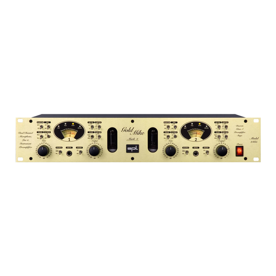
Dual-channel microphone and instrument preamplifier
PAD
PHANTOM
dB
-20
48 V
Off
Off
PHASE
HI PASS
Hz
Rev.
50
Mark 2
Nor.
Off
Gain
27 29
24
22
32
21
35
20
38
19
41
18
44
17
49
54
16
15
60
14
66
GoldMike Mk 2
Manual
VU CAL
LIMITER
dB
dB
Clip
Limit
-10
18
Off
48 V
AD OVL
0
12
7 5 3 1 0 3
FLAIR
TUBE AMP
10
5
20
dB
30
50 70
100
High
18
0
%
VU
Off
6
Med
12
2
Output
-9 -8
-10
-12
-6
-5
-14
-2.5
SOURCE
INSTR.
INSERT
-16
0
-18
Instr.
On
-20
2
Line
-22
3.5
Mic
Off
-24
5
-25
5.5
-26
6
Model 2485
Discrete
Class A
Preamplifier
Stage
Model
2485
Power
Advertisement
Table of Contents

Related Manuals for SPL 2485


Summary of Contents for SPL 2485
- Page 1 Line & Gain Output Gain Output 2485 Instrument 27 29 -9 -8 27 29 -9 -8 Power Preamplifier -2.5 -2.5 SOURCE INSTR. INSERT SOURCE INSTR. INSERT Instr. Instr. Line Line GoldMike Mk 2 Model 2485 Dual-channel microphone and instrument preamplifier...
- Page 2 This document is the property of SPL and may not be copied or repro- duced in any manner, in part or fully, without prior authorization by SPL.
-
Page 3: Table Of Contents
Contents Introduction ..............Before You Begin ............Rear Panel/Connections ..........Wiring ................. General advices ............Mic Input 1/2, Line In 1/2, Inserts 1/2 ......Outputs 1/2, GND Lift ..........Front Panel/Connections ..........Instr. Input 1/2 ............. Control Elements ............10 Power, Gain, About Gain Adjustments ...... -
Page 4: Introduction
You will not find any IC’s in this preamplifier stage because they cannot be optimized for this specific application to the degree we at SPL aim for. This all new discrete class A transistor stage is a genuine innovation in the entire preamplifier market at this price level. -
Page 5: Before You Begin
Before You Begin IMPORTANT: Before you operate your GoldMike MK2, first check carefully whether the local voltage setting corresponds to the switch setting on the rear panel! If not, and the voltage is in one way or another, incorrect, you VOLTAGE will either experience an immediate fuse burn through (if the 220 –... -
Page 6: Rear Panel/Connections
Rear Panel/Connections Wiring GoldMike MK2... -
Page 7: General Advices
Rear Panel/Connections General Advices Again, while the GoldMike MK2’s housing is EMV-proof and protects against HF-interference, placement of the unit is very important since it amplifies microphone signals as well as other unwanted signals. Before connecting the GoldMike MK2 or any other equipment turn off all power. -
Page 8: Mic Input 1/2, Line In 1/2, Inserts 1/2
Rear Panel/Connections Mic Input 1/2 INPUT Dynamic, condenser or tube microphones can be connected to the Mic inputs. The 48 V switch provides the phantom power necessary for some microphones (see also „Control Elements/ MIC INPUT 1 Phantom“ on page 11). Alternatively the GoldMike MK2 can be equipped with option- ally available transformer inputs from Lundahl (see “Lundahl Transformers“... -
Page 9: Outputs 1/2, Gnd Lift
Rear Panel/Connections Outputs 1/2 OUTPUTS XLR &TRS Jack: Balanced +4 dB Use Mono Jacks for Unbal. Operation The preamplifier signals are fed to these electronically balanced outputs. Alternatively the GoldMike MK2 can be equipped with optionally available transformer outputs from Lundahl (see OUTPUTS 1 “Lundahl Transformers”... -
Page 10: Control Elements
Control Elements Power Power You guessed that: with the Power switch the GoldMike MK2 is activated, verified by the illuminating switch. Please read “Before You Begin” on page 5 before throwing in for the first time. Gain Gain 27 29 The Gain control determines the pre-amplification of the micro- phone signal. -
Page 11: Output, Phantom
Control Elements Output Output -9 -8 This potentiometer adjusts the output level for devices following -2.5 in the chain or to the converter. The Output Level control allows an additional +6dB of amplification or -26dB of reduction. Output level values set with the output level control are not indi- cated by the VU meters, which indicate pre-amplification levels before this final stage. -
Page 12: Phase, Pad, Hi Pass
Control Elements Phase PHASE Rev. The phase reverse function reverses the polarity of the micro- Nor. phone signal, inverting the phase (by 180°) to correct phase- inverted signals caused by multiple signal sources. A voice- over artist, for example, hears himself during recording through the headphones and simultaneously through the bones in his head. -
Page 13: Flair, Tube Amp, About Tube Amping
Control Elements Flair FLAIR High As with its predecessor, the model 9844 GoldMike, the GoldMike MK2 features our sound-optimizing Flair circuitry. This circuitry takes advantage of a combined coil and tube filtering to enhance signal presence. In comparison to simple EQ manip- ulation, this intensified presence sounds very natural and unob- trusive, and is particularly suited for optimizing the overtones in voice and acoustic instruments. - Page 14 Control Elements Using the Tube Amp switch Engaging the Tube Amp switch tends to have a significant impact on the overall sound, as it directly changes the sonic character of the tube. The higher the Tube Amp value, the more you will have tube saturation and harmonic distortion, in addition to limiting effects.
-
Page 15: Limiter
Control Elements Limiter LIMITER The GoldMike MK2 offers a peak limiter that operates before the output level control. This ensures that the limited signal can be controlled as perfectly as possible for the internal—or an external—converter. The peak limiter operates with special diodes that convert signal peaks into a pleasant-sounding saturation. -
Page 16: Vu-Cal, Source, Display, Vu-Meter
Control Elements VU-Cal VU CAL The display range of the VU meter can be shifted using the -10dB VU Cal switch position. If the VU Cal switch is set to its 0 dB position and the output level control is also set to 0dB with the limiter switched off, the output level will effectively be 0 dBu.With the VU Cal set to -10 dB the 0 dB mark on the VU meter will represent a +10 dBu output level. -
Page 17: Led, Clip Led, Limit Led, Ad Ovl Led
Control Elements Display/48 V LED The 48V-LED indicates that the phantom power supply is acti- vated. The 48V-LED will slowly dim before going out to indicate that it takes some time for residual current to discharge. VERY IMPORTANT: The connection between microphone and GoldMikeMK2 should not be disengaged before the LED is completely dark! To avoid damages, please note also the phantom power supply usage information on page 11. -
Page 18: Technology
Technology Solid State And Tube Stages The solid stage preamp section is based on a fully discrete, balanced instrument amplifier and operates 12 single transis- tors in class A mode. A sophisticated circuitry ensures a nearly constant frequency response at any gain level. With an impres- sive slew rate of more than 200V/µs the solid stage is capable to amplify highest frequencies and fastest transients with almost no distortion, which is crucially important to achieve a realistic... -
Page 19: Instrument Input, Relays, Foil Condensers
Technology Class A Instrument Input The Instrument Input is a fully discrete impedance converter that also operates in class A mode. It is based on a low-noise field effect transistor that, due to its extremely high input imped- ance, is especially well suited to this task. Relay Switching In order to ensure the shortest possible signal paths, nearly all switching functions are handled by optimally positioned, encap-... -
Page 20: Power Supply
Power Supply In the case of the power supply, no expense was spared. After all, the power supply is one of the primary factors in the audio quality and overall sound of any device. Just like the best coffee beans in the world will not produce a good cup of coffee with poor water, the best circuits can’t produce a great sound with unreliable, inconsistent current. -
Page 21: Options (A/D Converter And Lundahl Transformers)
Options • 24-Bit/96kHz A/D converter (upgrades after sale can be done by clients). • Lundahl input and output transformers (upgrades after sale by authorized service personnel or SPL only). 24/96 A/D Converter SAMPLE RATE SYNC INPUT DIGITAL OUTPUTS 24/96 AD... - Page 22 Options Sync Input The SYNC input allows you to feed an external signal into the converter to control the sample rate. Connect an S/P-DIF output from your master source (e.g. sound card) to the SYNC input. The AD converter will automatically switch to the same sample rate that is received.
-
Page 23: Specifications/Dimensions & Weight
Specifi cations Frequency response ‹10 Hz to 90 KHz (-3 dB) Input impedances Microphone, XLR 2,8 KOhm Line In, TRS 10 KOhm Instr. In TRS 1 MOhm Output impedances XLR and TRS connectors 50 Ohm THD+N Input level Gain -30 dBu 30 dBu 0,016 % -40 dBu... -
Page 24: Warranty
SPL service personnel • the serial number has been removed or defaced In no event shall SPL be liable for any indirect, incidental or consequential damages from the sale or use of this product, either during or after the warranty period.
Need help?
Do you have a question about the 2485 and is the answer not in the manual?
Questions and answers