Table of Contents
Advertisement
Quick Links
Download this manual
See also:
Operator's Manual
Advertisement
Table of Contents
Troubleshooting

Related Manuals for International Harvester Company CUB


Summary of Contents for International Harvester Company CUB
- Page 2 SAFETY INSTRUCTIONS This symbol is used to coil your attention to instructions concerning your personal safety, Be sure to observe and follow these instructions. roadways. Disengage all clutches and shift into neutralbefore Watch out for traffic when crossing or near starting the engine.
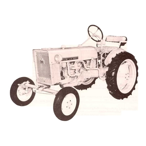
- Page 3 Ilrust.2 International Cub La-Bay Tractor. Assembled in this manual operation, Depending upon your use of the tractor, lubrication, and maintenance instructions these inspections should be performed International and Cub Lo-Boy Tractors. needed, or at least once a year, at which time...
- Page 4 INTRODUCTION In order to provide a tractor equipped nearly as possible to suit each customer's needs, a variety of extra equipment and acces- sories is available. Refer to page 76. Where operating and maintaining instruc- tion on these items is required, it is included in the instructions for operating...
- Page 5 Illust.4 Instruments and controls (12.volt system). -BRAKE PEDALS These pedals are used to stop the tractor, to hold the tractor in a station- ary position, or to assist in making sharpturns. The brake pedal latch (behind the left brake pedal) is used to latch both brake pedals together,...
- Page 6 INSTRUMENTS AND CONTROLS BRAKE PEDALS -Continued ENGINE SPEED CONTROL LEVER Caution! Always latch the brake pedals This lever controls the speed of the engine together when driving the tractor in high and, when set in a given position, will maintain gear.
- Page 7 INSTRUMENTS AND CONTROLS IGNITION SWITCH BUTTON (6-Volt System) This button (1IIust. 4A) closes and opens the electrical circuit for operating and stopping the engine. Pull the button out for operatingand push it in to stop the engine. Note: On tractors with battery ignition, when the engine...
- Page 8 Tractors packed for export have all oil TRACTOR BREAK.IN PROCEDURE drained from the engine crankcase, air cleaner Never operate an engine immediately under and all gear cases. full load. Break it in carefully, no load, light load, and medium engine load for the first 25hours.
- Page 9 cleaner cap. Remove any dirt or chaff. cleaner oil cup Remove, clean and refill. See the "Lubrication Guide. Lubrication points. See "Lubrication Guide. " Cooling system. Check the level of the coolant in the radiator. FILLING THE FUEL T AHK Do not smoke or use an oil lantern when...
- Page 10 Before attempting to start or operate the tractor, be sure you review the instructions for the new tractor and thoroughly famil- iarize yourself with the instruments and controls. This engine is designed to operate on gasoline with a 90 minimum octane rating (Research Method). The use of unleaded gasoline will lengthen spark plug and valve life, maintain engine performance longer, and reduce rust and corrosion of engine while stored.
- Page 11 GASOLINE ENGINE STARTING THE ENGINE -Continued retor choke lever down all the way. See !llusts. 9 and 9A. Do not use the choke to enrich the fuel Note: Never operate the cranking motor mixture, except when starting the engine. while the engine is rotating.
- Page 12 ADJUSTING THE SEAT (International Cub La-Boy) Before starting the tractor, adjust the seat to the most comfortable position of the fourpositions available to the operator. The seat is quickly...
- Page 13 DRIVING THE TRACTOR ADJUSTING THE SEAT (International Cub Lo-Boy) -Continued made. The brake pedals must be unlatched so they can be operated individually. TOWING THE TRACTOR When towing is necessary, cuse a rope, chain, or cable and have an operator...
- Page 14 Illust.13 Touch.Control system. The Touch-Control system is ready to oper- The control lever ('Ilust. 13) gives the operator ate whenever the engine is running. You will complete, instantaneous and effortless control receive the maximum of satisfactory service of all the direct-connected equipment operating by closely...
- Page 15 TOUCH-CONTROL SYSTEM The working depth will be maintained trol lever stop at a point where the raised moving the lever back to the stop each timethe equipment will not hit the underside of the equipment is lowered. tractor. AIR IN THE SYSTEM After attaching the equipment to the trac- tor, the Touch-Control lever front stop must...
- Page 16 See IlLiquid Weights" under "Fast-Hitch Load Limitations". Illust. Rear view af International Cub Troctor with Fost.Hitch.
- Page 17 FAST-HITCH Illust. Rear view of International Cub La.Bay Tractor with Fast.Hitch.
- Page 18 -use a rear wheel tread setting up to 56-inches. International Cub Lo-Boy -use a rear wheel PULL BAR EXTENSION tread setting up to 56-inches with the front tire tubes filled three-quarters...
- Page 19 "B" (1!lust. 18A), and raise or lower complete drawbar. drawbar to the upper or lower hole in the draw- The drawbar on International Cub tractors bar bracket. Replace bolts "B" and tighten can be reversed and placed in the forward curely.
- Page 20 Observe the direction of belt travel in- dicated on the belt. and install the belt Note: When the International Cub Lo-Boy accordingly to prevent damaging it. tractor is equipped with the Fast-Hitch, Tighten the belt enough to prevent the belt from rubbing against itself during operation.
- Page 21 BELT -PULLEY AND POWER TAKE-OFF OPERATING THE POWER TAKE-OFF WITH TRACTOR Replace the removed cap screws with the MOTION extra cap screws supplied with the belt pulley and power take-off. Use two 3/8 N. C. x 1-3/8- Follow the first four steps outlined above;...
- Page 22 The thermo- siphon principle is used for The gasket surfa...~ must be in good condi- circulating water in the cooling system. (The tion. The cap must be properly tightened temperature of the water governs the rate of the stop, and the system must not have loose circulation.) Therefore,...
- Page 23 COOLING SYSTEM ADDING WATER TO THE COOLING SYSTEM (When Equipped with Pressure-Type Radiator Cap) -Continued Allow the engine to cool and fill the radiator plug on the bottom (center) of the radiator slowly to approximately 2-inches below the (1IIust.22). Allow the system to drain;...
- Page 24 COOLING SYSTEM RUST PREVENTION. Continued For rust prevention during winter use of the engine, a fre sh filling of antifreeze con- taining an effective corrosion preventive should be used. In the spring, drain and dis- card the old antifreeze solution, as the rust preventive or "inhibitor"...
- Page 25 COOLING SYSTEM GENERA TOR BELT After the fan belt tension has been adjusted, move the generator toward or away from engine to get the correct generator belt tension; then tighten nuts I'A'! and "B" (1IIust. 23A). The generator belt should be tight enough as not to allow slippage, but not so tight as to cause...
- Page 26 Clean and reoil this breather each Illust. 25 time the engine oil is changed. Exploded view of air cleaner. International Cub Tractors with serial num- tions. Be sure all terminals are clean and se- bers 224401 and up or International...
- Page 27 Illust.26A Battery and cables (6-valt system shawn an International Cub LaBoy Tractor). Note: on the twelve-volt battery the negative (-) terminal is the ground and on the six-volt battery the positive (+) terminal is the ground.
- Page 28 ELECTRICAL SYSTEM SPARK PLUGS AND CABLES. Continued MAGNETO Greasing the Breaker Mechanism and Checking the Points (1Iust.27A Illust.27 Adjusting the breake, points. Spark plug wiring. Engine firing order Is 1. 3, 4. 2. (Magneto shown on the engine.) It is important that the breaker chamber kept clean,...
- Page 29 ELECTRICAL SYSTEM MAGNETO. Continued Illust. 28 Magneto disassembled. Greasing the Breaker Mechani sm and Checking the thoroughly clean and wipe dry. To assure long Points. Continued life of the distributor, care must also be taken to keep the three small ventilator holes in the...
- Page 30 ELECTRICAL SYSTEM MAGNETO. Continued Removing the Magneto Illust. 29A !llust. 29 Magneto wiring (clockwise rotation). Removing the mogneto. Firing order 1,3,4,2. 3. Assemble the magneto on the engine, making sure that the lugs on the impulse cou- 1. Disconnect switch cable "A"...
- Page 31 ELECTRICAL SYSTEM DISTRIBUTOR AND COIL UNIT MAGNETO. Continued Installing and Timing the Magneto to the Engine Greasing the Breaker Mechanism and Checking the Paints .Continued Illust. 30A 1(lust. 30 Magneto removed showing Impulse coupling. Adlusting the breaker paints. Tighten mounting clip nut "D"...
- Page 32 ELECTRICAL SYSTEM DISTRIBUTOR AND COIL UNIT. Continued Greasing the Breaker Mechanism and Checking the P.oints .Continued Illust.31 Distributor partially disossembled for servicing. Check the condition of the breaker points If the spark plug cables have been removed for any reason, attach the cables to the spark...
- Page 33 ELECTRICAL SYSTEM POWER TIMING LIGHT adjustment or attention. If the regulator failsto operate correctly, see your International Harvester dealer. POLARIZING THE GENERATOR If the generator or the regulator has been removed or the leads disconnected, the gener- ator should be repolarized. After the leadshave been reconnected,...
- Page 34 ELECTRICAL SYSTEM COMBINATION REAR LIGHT AND TAILLIGHT FUSE A cartridge-type fuse is located in the fusehousing. The combination rear light and taillight If a short circuit occurs in the light- turned on by the lighting switch on the instru- ing circuit, the fuse will burn out and break ment panel and gives...
- Page 35 ELECTRICAL SYSTEM STORAGE BATTERY. Continued Example No.2 Hydrometer reading. 1.255 Liquid Level -Continued Electrolyte temperature. +lOOoF. Add .008 Sp. Gr. (.004x2) For dependable battery service see your Corrected Sp. Gr. is. 1.263 International Harvester dealer. Use Ccn accurate hydrometer when testing for specific gravity.
- Page 36 ELECTRICAL SYSTEM "A"tenninal "1 2"".- Tape (9 8 13 ~7 28 24 19 7~12 Negative terminal , "===I~ To mogneto / ignition switch ~- 0, 1 " ~~-;id;~~"",,-~ 10 11 of the tractor Headlight cables grounded the generator rear bracket bolt 15 25 ..-!..
- Page 38 ELECTRICAL SYSTEM Index to reference numbers in II lust. 36 Ref. Ref.No. Description Description Cable -starting switch to cranking motor Cable ~ battery to starting switch Cable -regulator "BAT" terminal Battery charge indicator negative (-) terminal Strap ~ battery to ground (ground battery box left...
- Page 39 ELECTRICAL SYSTEM Top view of battery box and taillight -"'l < I/\~\ .ry \ ""~ ' '~~~ \.~" .._~~..~ " ..~/ -II.. -='_~, '-.,- " ". ---J ",\ ,~-~' "1 - " ~J I ,... Left side view Headlight cables grounded on the generator rear bracket...
- Page 40 ELECTRICAL SYSTEM Illust. Electric starting and lighting wiring diagram for tractors equipped with magneto ignitions (6.volt electrical system). Ref. Ref. Description Description Cable -battery to starting switch Headlights Magneto ignition switch Cable harness -rear light 2021 Cable -regulator I'BA TII terminal Cable -taillight to junction...
- Page 41 ELECTRICAL SYSTEM View of voltage regulator showing connections 8-12888 Illust.40 Electric starting wiring diagram for tractors equipped with battery ignition (6.volt electrical system). Ref.1 e f . Description Description No.1 Battery ignition switch Cable -regulator "BAT" terminal charge indicator positive terminal -gray (.-able -regulator...
- Page 42 ELECTRICAL SYSTEM Rear view showing taillight 8-12887 Illust.41 Electric lighting wiring diagram for tractors equipped with battery ignition (6-volt electrical system). Ref. Description Description Fuse housing Cable harness -rear light Cable -"RL" terminal to rear light taped Cable -fuse housing to lighting switch at rear...
- Page 43 CYLINDER HEAD GASKET Adjusting the Clearance Check the tightness of the cylinder head 1. To safeguard against accidentally starting bolts after the first 50 hours of engine opera- the engine when checking the valve clearance, tion for a new tractor and 50 hours after in- remove cable liB"...
- Page 44 MINOR ENGINE SERVICE OPERATIONS VALVE CLEARANCE ADJUSTMENT -Continued Adlusting the Clearance -Continued 7. Replace the valve cover. Check to see that the valve cover gasket makes an oiltight seal with the crankcase. Replace the gasket if necessary. 8. Replace magneto cable lIB"...
- Page 45 See Illust. 44A. The wheels are provided with mounting holes for the addition of cast iron wheel weights. International Cub La-Boy Tractor Each wheel is mounted on the hub with five The front wheels can be adjusted to treads special bolts...
- Page 46 FRONT WHEELS ADJUSTABLE WIDE-TREAD FRONT AXLE -Continued Adjusting the Toe-in The front wheels should have 1/4 inch Adjusting the Tread Widths 1/16-inch) toe-in (1/4-inch closer in front than in the rear). To check the toe-in, place Raise the front end of the tractor. chalk marks at point I'G"...
- Page 47 The rear wheels are steel disc wheels with graphs. wheel treads described in the following para- demountable rims for tractor-type agricul- tural tread tires and are provided with mount- ADJUSTING THE TREAD WIDTHS ing holes for the addition of cast-iron wheel weights.
- Page 48 REAR WHEELS 1(lust.47 Rear wheel tread positions.
- Page 49 FRONT WHEEL WEIGHTS (One-Piece) The one -piece front wheel weights weigh Thefirst set of front wheel weights includes approximately 26 pounds each, and either a set of two weights and four 1/2NC x 1-3/4- or two can be attached to the outside of each inch bolts, nuts and lock washer s for attaching...
- Page 50 FRONT WHEEL WEIGHTS (Two-Piece) -Continued Two-piece front wheel weights are available The rear wheel weights weigh approximately to provide additional weight for the front end ofthe 150 pounds each and either one or two can be tractor when operating over hilly ground attached...
- Page 51 Observe the following instructions and rec- ommendations in order to secure maximum life and efficient service from the pneumatic tire s. CARE OF TIRES Avoid stumps, stones, deep ruts, other hazards. Cuts in tires should be re-" paired immediately, as neglect decreases tire life.
- Page 52 PNEUMATIC TIRES OPERATING PRESSURE FOR LOW.PRESSURE TRACTOR TIRES. Continued TRACTION AND WEIGHTS Rear Tire Loads in Pounds at Various The tractor should not be operated with the Inflation Pressures tires improperly inflated. To insure the max- Underscoring indicates maximum recommended load per tire. imum hours of service, watch the tread lugs;...
- Page 53 BRAKES BRAKE ADJUSTMENT. Continued Replace pin "A" and tighten lock nut "B'! after the adjustment has been completed. It is very important to have the brakes equalized. To have equalized brakes. both pedals must have the same amount of free mo ve ment.
- Page 54 ADJUSTING THE ENGINE CLUTCH. Continued Edge of platform to pedal 1/8" Clearance Wear utch IS/~ """"""" ""I ~/,zzzr, 'clutch pilot Lubricatiay ((\~).y'- fitting 5/16/ bearing \ailless bushing) Full lever travel Hand hale cay 8-4523A Illust. 53 Clutch adjustments. When your tractor is not to be used for clean the tires thoroughly.
- Page 55 STORING THE TRACTOR Note: Gum will eventually form in the fuel mixture of one-half kerosene and one-half tanks, lines, and carburetor if the unit is notused. SAE-IOW engine oil. Gum in carburetor jets and passages affects engine starting. Gum can be dissolved 4.
- Page 56 When operating the tractor in temperatures If an antifreeze is to be used: of +32 degrees F. or lower, observe the fol- 1. Inspect the hose connections. They must lowing precautions: be in good condition both inside and out. Then tighten all water connections.
- Page 57 Problems and their Probable Cause If any trouble is experienced, make sure of the cause before attempt- ing to make any adjustments. When making an adjustment, keep in mind the previous setting in case the adjustment doesn It solve the problem. Possible Couse Possible...
- Page 58 TROUBLE SHOOTING Possible Remedy Possible Cause OF POWER Engine speed control lever not advanced. Advance the engine speed control lever. Engine cold or overheated. Run the engine until it warms up before putting it under load. Check the cooling system. Engine overloaded.
- Page 59 TROUBLE SHOOTING Possible Cause Possible Remedy OIL DILUTION OR USES TOO MUCH OIL Oil of incorrect viscosity. See the "Lubrication Table" on page 65. Leaks in oil lines or filter or in oil pan plug or gasket. Check and tighten. Worn piston or oil rings.
- Page 60 TROUBLE SHOOTING Possible Remedy Possible Couse IGNITION AND ELECTRICAL. Continued Battery defective, low charge or loose connections. Recharge, clean and tighten the cable lugs or replace with new; check the ground cable; see pages 33 and 34. Cranking motor failure. Replace.
- Page 61 TROUBLE SHOOTING Possible Remedy Possible Cause STEERING Check the steering worm and gear; check the front axle adjustment; see pages 44 and 45. Check the lubricant in the front wheel. Check the tire inflation. Defective front axle. Inspect the linkage, check and replace faulty parts.
- Page 62 LUBRICA TION TO AID ST ARTIHG CRANKCASE BREATHER AND OIL FILLER CAP -Continued To facilitate starting, selection The crankcase oil filler cap has a bayonet- crankcase lubricating oils should be based type oil level gauge attached to it. The oil lowest anticipated temperature...
- Page 63 LUBRICA TION OIL FILTER. Continued Ii the element is not serviced and becomes 3. Unscrew and remove bolt "B" and gasket clogged, the element by-pass valve will open "G" (1!lust. 62). and wrliltered oil will be circulated throughthe engine. 4. Lift up and remove filter cover...
- Page 64 LUBRICA TION OIL FILTER -Continued Never operate the tractor without having sufficient fluid in the reservoir. Insufficient Changing the Filter Element -Continued fluid may cause damage to the Touch-Control system. 8. To install the new filter element, move Note: Failures due to use of improper gasket "C"...
- Page 65 LUBRICATION TOUCH CONTROL SYSTEM -Continued Draining and Filling the Reservoir -Continued Now remove the four cap screws which hold the strainer to the cylinder block, and pull out the screen. Clean the strainer thor- oughly in clean ill Hy-Tran Fluid. Then replace the strainer and make sure the gasket is in perfect condition.
- Page 67 International Cub Tractor The symbols around the reference numbers indicate the intervals of lubricotion. 10 hours, --250 hours, --SOD hours, § -4--_J "'""'/ -~~~~. ..::P:::~ ~ 'u1' " O> " "':::~:::~- ~ 7, ."$~ ,. -, ..c" ~~?-~ "'- """"""~...
- Page 68 LUBRICATION GUIDE International Cub Lo-Boy Tractor The symbols around the reference numbers indicate the intervals of lubrication. hours, ~,,~~~, 1iI-- ,+ji~ --~t:::,]~ '-r-' I.-l-~~ ~ ,- , ":'i >- ~.~d ,... I " C..0 "> "" c:::: ~" /'" ---""...
- Page 69 LUBRICATION GUIDE symbols around the reference numbers indicate the intervals of lubrication. hours, -50 hours, -periodic Cub Tractor 8-91338 Illust. 68 -Fast-Hitch. International Cub Lo-Boy Tractor " --=-:1 ,i;. A-48002C Illust. 68A -Fast-Hitch. "" .& ..., International...
- Page 70 Seat spring cient grease to flush out the old grease and dirt. (International Cub) Lubricate the clutch and brake pedal connections with a few Miscellaneous parts drops of engine oil.
- Page 71 LUBRICATION GUIDE -After Every 100 Hours of Operotion While the oil is warm, remove the crankcase drain plug and oil filter drain pipe cap and drain all of the oil from 18. Crankcase oj I pan. crankcase and oil filter. Replace the drain plug and cap.
- Page 72 LUBRICATION GUIDE Periodic Twice a year (spring and fall) remove, clean, and repack front wheel bearings with IH-251 HEP grease or equivalent 27. Front wheel s. 1#2 multi-purpose lithium grease. Check the oil level periodically. Keep the lubricant up to level plug (29) on the left side of the transmission case.
- Page 73 To keep your tractor performing efficiently, it is advisable to systematically inspect the following points at intervals as outlined below. Before Operating the Tractor Before operating a new tractor first time, be sure to follow instructions given on page 7; also Lubrication Section on pages 60 to 71.
- Page 74 PREVENTIVE MAINTENANCE GUIDE After Every 50 Hours of Operation Flexible rubber connection between cleaner and carburetor or manifold. fuspect for loose fit or leakage. See page 25. Pneumatic tires. Check pressure. See pages 50 and 51. Radiator core. fuspect. cl~an if necessary. See page 23.
- Page 75 9-3/4 qt. 3 qt. 3-1/2 pt. 1- 1/2 pt. rlve ouslng International Lo-Boy. 1-3/4 pt. Steering Aircleaneroilcup(Donaldson) gear housing. Internatlonal Cub. .Air 3/4 pt. 1/ 2 pt. 3/8 pt. Belt Touch-Controlsystem cleaner pulley housing. (United) 1/3 pt. 4-1/4 pt. ENGINE Bore.
- Page 76 6-8 volt 12-16 voltAGC-I0 (cartridge type) SFE-20 amp. amp. CLUTCH 6 -1/ 2 in. Single-plate, dry-disc, spring-loaded. FOOT BRAKES External contracting on drums. rnational Cub Lo-Boy WHEELS TREAD t4.00-12 t4.00-12 Wheelbase Front Rear Tread, wheels, wheels. front (standard-fixed pneumatic pneumatic...
- Page 77 52,53 belt pulley. Charge Chokerod Cleaning Cleaning indicator. cooling fuel strainer system. Adjusting widths seat (International Cub) Adjusting seat (International Cold Clutch Clutch Combination sedimentbowl weather pedal rear precautions. light tail- Adjusting Lo-Boy) tread widths (Rear...
- Page 78 INDEX Page Description Description to 41 Electrical Engine Engine Extra equipment cooling oil. speed system. control system. Engine accessories. lever. Operating Oilpump pressure filter service. pressure gauge. low- 61 to 63 50, 5: Operating pressure tractor belt tires. pulley power Filling Filling Fanbelttension...
Need help?
Do you have a question about the CUB and is the answer not in the manual?
Questions and answers
Do you have any information on the lawn mower attachment used on a Farmall Cub Lo-Boy