Table of Contents
Advertisement
Advertisement
Table of Contents

Subscribe to Our Youtube Channel
Related Manuals for International Harvester Company C-2


Summary of Contents for International Harvester Company C-2
- Page 2 Your new International Harvester rotary mower is designed to meet today's exacting operating requirements. The ease of operation and ability to adjust to field conditions lighten your work and shorten your hours on the job. You are urged to consult your International Harvester dealer con- cerning unusual field conditions or special applications.
- Page 5 INTRODUCTION The International C -2 Rotary Mower is Heavy duty V -belt drive designed for use on the International @ Cub Non-wrap spindle 2 spring steel reversible blades Lo-Boy@, McCormick@ Farmall Cub@ 2 high speed tapered roller bearings and International 140 Tractor.
- Page 6 GENERAL BELT ADJUSTMENT Before using, carefully lubricate the Center-Mounted Mower mower. Check all bolts for tightness and see that all cotter pins are spread. Always adjust the belt tension when the platform is in a down position. Check the tightness of the drive belt with the platform lowered to cutting position.
- Page 7 ADJUSTING AND OPERATING STARTING AND STOPPING THE MOWER LUBRICA TION Throttle down the engine before engaging Always lubricate the mower thoroughly or disengaging the power take-off. This will before taking it to the field. reduce the wear on the main drive belt as well as the tractor clutch.
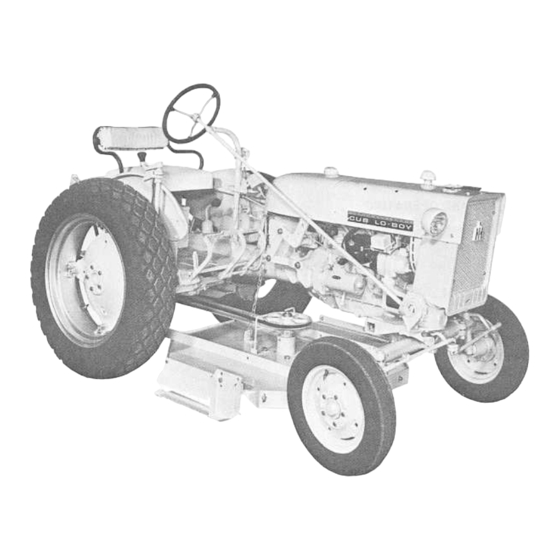
- Page 8 Remove all wires. Sort out all hardware INTERNATIONAL CUB La-BOY TRACTOR by sizes and types in a convenient and or- derly manner. 1. Attach the idler bracket assembly to the tractor differential housing. When Lubricate all bearings and moving parts securing bracket, replace the tractor bolts as you proceed, and see that they work...
- Page 9 SETTING UP INTERNATIONAL CUB LO-BOY TRACTOR washer, and nut. Note: The three pivot bushings must be properly inserted into the linkages to permit them to have a free .pivoting action. See Illust. 7A. Attach the chain to the lift chain arm and to the angles on the platform.
- Page 10 SETTING UP FARMALL CUB TRACTOR (Without Fast-Hitch) Illust.8A Note: For ease in mounting, position the drawbar to the lowest adjustment with the adjusting bolts extending toward the wheels. Illust.88 1. Mount the idler mounting bracket in- side the drawbar, using the four 5/8 x 1-1/2 4.
- Page 11 SEmNG UP FARMALL CUB TRACTOR (Without Fast-Hitch) -Continued 7. Attach the lift chain arm to the tractor 9. To mount the belt guides, remove the right rocks haft arm, using two 5/8 x 1-3/4 left and right rear cap screws, and lock inch hex.
- Page 12 SETTING UP FARMALL CUB TRACTOR (With Fast-Hitch) Note: The pull bar on the hitch must be moved to the furthest right hand setting. 1. Attach the rear mounting bracket as- sembly on the inside of the Fast-Hitch side casting. The two spacer plates provided in the kit must be positioned between the Fast- Hitch casting and the mounting bracket to allow proper clearance.
- Page 13 SETTING UP FARMALL CUB TRACTOR (With Fast-Hitch) -Continued Il/ust. For correct belt tension the platform must be in a down position. Adjust the V -idler downward Illust. llA until belt is stretched tight. 11. To mount the belt guides, remove the 10.
- Page 14 SETTING UP INTERNATIONAL 140 TRACTOR Note: Tractors with Fast-Hitch: The pull bar on the hitch must be moved to the furthest left hand setting. 2. Attach the pivot brackets to the inside of the legs extending downward on the rear 1.
- Page 15 140 TRACTOR 5. Attach the flat idler swivel bracket should be positioned in a direct line with the assembly to the rear mounting bracket, usingtwo rear drive sheave and in line with the right 1/2 x 1-1/2" hex. head cap screws, flat hand side of the platform spindle sheave.
- Page 16 SETTING UP 5. Attach the transfer spindle assembly REAR FAST-HITCH MOWER (Used only on International Cub Lo-Boy and Farmall Cub to the spindle and idler mounting bracket, using four 1/2 x 1 II hex. head cap screws, Fast-Hitch Tractors) lock washers, and nuts. 1.
- Page 17 SETTING UP 10. Mount the tail wheel arm assemblies to the platform lift angles, using two 1/2 x 1-1/2" hex. head cap screw, lock washers, and nuts for each arm. 11. Mount the wheel and wheel arm assem- blies to the tail wheel arms with 1/2 x 1-3/4 inch clevis pin, flat washer, and 5/32 x 1 inch cotter pin.
- Page 18 Possible Cause Possible Remedy VIBRA TION Check all bolts and nuts for tightness. Loose Blades mounting balance. bolts. Inspect blades for damage. Remove and sharpen evenly, or replace with new blades. See page 5. Bent spindle shaft Replace shaft. UNCUT STRIPS Adjust belt tension.
Need help?
Do you have a question about the C-2 and is the answer not in the manual?
Questions and answers