Table of Contents
Advertisement
Operating
Instructions
Thank you for buying this Pioneer product.
Please read through these operating instructions so you will
know how to operate your model properly. After you have
finished reading the instructions, put them away in a safe place
for future reference.
In some countries or regions, the shape of the power plug and
power outlet may sometimes differ from that shown in the
explanatory drawings. However, the method of connecting and
operating the unit is the same.
IMPORTANT NOTICE
[For U.S. and Canadian models]
The serial number for this equipment is located on the rear
panel. Please write this serial number on your enclosed warranty
card and keep it in a secure area. This is for your security.
[For Canadian model]
CAUTION:
TO PREVENT ELECTRIC SHOCK DO NOT USE
THIS (POLARIZED) PLUG WITH AN EXTENSION CORD,
RECEPTACLE OR OTHER OUTLET UNLESS THE BLADES CAN BE
FULLY INSERTED TO PREVENT BLADE EXPOSURE.
ATTENTION:
POUR PREVENIR LES CHOCS ELECTRIQUES
NE PAS UTILISER CETTE FICHE POLARISEE AVEC UN
PROLONGATEUR, UNE PRISE DE COURANT OU UNE AUTRE
SORTIE DE COURANT, SAUF SI LES LAMES PEUVENT ETRE
INSEREES A FOND SANS EN LAISSER AUCUNE PARTIE A
DECOUVERT.
AUDIO/VIDEO STEREO RECEIVER
N∫m¿Û≤∫
N∫m¿Û≤∫
AUDIO/VIDEO STEREO RECEIVER
STANDBY
SR
RETURN
RESET
POWER
STANDBY/ON
VCR 1
VCR 2
VIDEO
TV/SAT
SPEAKERS
B
A
SLEEP
DIRECT
DOLBY SURROUND
AC-3 P R O • L O G I C
PHONES
VIDEO
L
AUDIO
R
VIDEO
INPUT
Intelligent System Control
MULTI-JOG
AC-3
TAPE 2
PHONO
LD
TAPE 1
TUNER
CD
MONITOR
TUNING MODE
FM/AM
MPX MODE
MEMORY SELECT
DOLBY
DSP OFF
PRO-LOGIC
DSP MODE
SURROUND MODE
DEMO MODE
¶The demonstration mode is activated by turning on the
power switch while holding down the RETURN button
(from power standby condition). The demonstration will
appear on the display.
¶Press any button to cancel the demonstration. Activating
the demonstration mode causes memory contents to return
to their original default condition, except the tuner.
U.S. and Canadian models
Multi-voltage model
WARNING:
NOT EXPOSE THIS APPLIANCE TO RAIN OR MOISTURE.
RETURN function
This function returns the unit to its initial settings with the
tuner ready to receive a broadcast. This is helpful during
troubleshooting or when no sound is output. For details,
refer to page 13.
RESET function
Set the MASTER VOLUME to minimum before pressing the
RESET button.
Use this function when normal operation is not possible due
to external influences such as static electricity or lightning, or
when operations are not functioning even when the operation
switches are pressed. Press the RESET button to return to
normal operating conditions.
MASTER VOLUME
INPUT
ATT
GUI
MODE
GUI
ENTER
MIN
MAX
SUPER
BASS
TREBLE
SUPER BASS
BASS
–
+
–
+
FLAT
MAX
NTSC
NTSC/PAL
TO PREVENT FIRE OR SHOCK HAZARD, DO
Advertisement
Table of Contents

Related Manuals for Pioneer VSX-D3S


Summary of Contents for Pioneer VSX-D3S
- Page 1 SURROUND MODE Intelligent System Control DEMO MODE Thank you for buying this Pioneer product. Please read through these operating instructions so you will ¶The demonstration mode is activated by turning on the know how to operate your model properly. After you have...
-
Page 2: Safety Instructions
— WATER AND MOISTURE The appliance should not should be serviced by a Pioneer authorized service an antenna discharge unit, size of grounding be used near water – for example, near a bathtub, center or qualified service personnel when: conductors, location of antenna discharge unit, •... -
Page 3: Table Of Contents
INSPECTION CHECKLIST CONTENTS The Pioneer Receiver is packaged with the following BEFORE OPERATING items: INSPECTION CHECKLIST ............3 INSTALLATION ................4 SETTING THE SWITCHES FOR THE MULTI-VOLTAGE MODEL ONLY ...... 4 INSTALLATION PRECAUTIONS ..........5 FM T-type antenna CONNECTIONS ANTENNA CONNECTIONS ............ 6 AUDIO SYSTEM CONNECTIONS .......... -
Page 4: Installation
INSTALLATION SETTING THE SWITCHES FOR THE MULTI-VOLTAGE MODEL ONLY TWO VOLTAGE SELECTOR SWITCHES CHANNEL STEP/FM DE-EMPHASIS SWITCH (Not available on U.S. and Canadian models) (Not available on U.S. and Canadian models) The unit has been factory preset to the channel allocation and Only multi-voltage models are provided with these de-emphasis value for the area in which it is to be sold. -
Page 5: Installation Precautions
÷ Do not place the unit on top of your TV set or TV monitor. Also, cord once in a while. When you find it damaged, ask your keep the unit away from devices such as cassette decks which nearest PIONEER authorized service center or your dealer for a are sensitive to magnetic fields. replacement. -
Page 6: Connections
CONNECTIONS ANTENNA CONNECTIONS Setting Up the AM Antenna ÷ Insert the claw on the bottom of the antenna into the NOTE FOR FM ANTENNA: groove in the leg. ÷ Place the antenna on a level surface and rotate it to locate Stretch the antenna out to its full length and affix it to a wall, etc. -
Page 7: Audio System Connections
AUDIO SYSTEM CONNECTIONS NOTE: Dolby Surround will not operate correctly if the signal passes Connect when using a PIONEER projection monitor through a graphic equalizer. receiver's built-in speaker as a center speaker. When using Dolby Surround, turn off the TAPE 2 MONITOR... -
Page 8: Video System Connections
CONNECTIONS VIDEO SYSTEM CONNECTIONS THE S-VIDEO CONNECTORS When using the VCR 1, LD and TO MONITOR TV jacks with FRONT PANEL FRONT PANEL components which have S-VIDEO connectors, they can be connected to the S-VIDEO connectors. SLEEP DIRECT DOLBY SURROUND AC-3 P R O •... -
Page 9: Speaker System Connections
CONNECTIONS SPEAKER SYSTEM CONNECTIONS You can set this unit to match the requirements and specifications of your stereo system’s speakers (whether or NOTE: not center speaker(s), rear speakers or a sub-woofer are Use speakers with an impedance of 8 to 16 used, speaker size, etc.) to assure optimum sound quality. -
Page 10: Ir Repeater Connection
Connecting a supplied IR Repeater lets you also control other components with this unit’s remote control. NOTE: To operate components not made by Pioneer, perform REMOTE SET UP (page 31) after connecting an IR Repeater. Remote control signals directed towards this unit or GUI operation signals are transmitted from the repeater as infrared signals, enabling control of other components. -
Page 11: Rear Panel Facilities
= CENTER PRE OUT jack OUT : Connect this jack to other Pioneer components when Connect when using a PIONEER projection monitor receiver's using the remote control of this unit to control the other built-in speaker as a center speaker. -
Page 12: Power Cord
REAR PANEL FACILITIES ~ TWO VOLTAGE SELECTORS switches ) REAR SPEAKERS terminals (Multi-voltage model only) Connect the rear speakers to these terminals. NOTE: See page 4. Do not allow any of the cord’s conductors to protrude from the terminals or touch any other conductors. Malfunctions or ! TAPE 1 jacks breakdowns may occur when conductors come into contact Connect to the first cassette deck. -
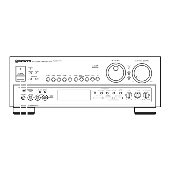
Page 13: Front Panel Facilities
FRONT PANEL FACILITIES N∫m¿Û≤∫ MULTI-JOG MASTER VOLUME AUDIO/VIDEO STEREO RECEIVER AC-3 INPUT STANDBY RETURN RESET MODE POWER STANDBY/ON VCR 1 VCR 2 VIDEO PHONO TV/SAT TAPE 1 TAPE 2 TUNER SPEAKERS MONITOR ENTER TUNING MODE SLEEP DIRECT SUPER BASS TREBLE SUPER BASS DOLBY SURROUND FM/AM... - Page 14 FRONT PANEL FACILITIES 9 MULTI-JOG Auto stereo mode Normally, leave in this mode for reception. When a stereo FM Use during tuner operation to select frequencies and station broadcast is received, it will be automatically reproduced in numbers. During GUI operation, use to move the on-screen stereo.
-
Page 15: Display Section
FRONT PANEL FACILITIES DISPLAY SECTION DSP MODE DOLBY DOLBY J A Z Z D A N C E H A L L SURROUND PRO LOGIC SIM SURR THEATER AC-3 SUPER BASS ST CALL MONO TUNED STEREO TAPE 2 A LFE indicator H ATT indicator During Dolby AC-3 mode operation, if the LFE (Low Frequency This lights when the INPUT ATT button is on. -
Page 16: Operating The Tuner
OPERATING THE TUNER Press the POWER switch to the ON position. FREQUENCY PRESETTING Select TUNER with the input selector button. Be sure to turn the TAPE 2 MONITOR button off when listening to AM or FM broadcasts. 2, 4 GUI MODE Switch on the SPEAKERS button corresponding to the speakers you wish to use. -
Page 17: Receiving Fm Simulcast Tv Programs
OPERATING THE TUNER NOTE: RECEIVING FM SIMULCAST TV PROGRAMS Even if the receiver’s power cord is unplugged, data remains in memory for several days. If the contents of the memory are By combining a TV set with this receiver, you can receive FM erased, preset once more. -
Page 18: Recording With A Cassette Deck
RECORDING WITH A CASSETTE DECK RECORDING WITH TAPE 1 USING VCR 1, VCR 2 FOR AUDIO RECORDING If the TAPE 2 MONITOR button is on, press to turn off. The audio signal output from the VCR 1 and VCR 2 AUDIO OUT jacks is the same as that output from the TAPE 1 REC jacks, so you can record using the same procedure as for recording with TAPE 1. -
Page 19: Video Recording
VIDEO RECORDING Refer to the connection procedures on pages 8 to 10 and refer 2. Start recording on the VCR. to the VCR’s Operating Instructions regarding proper operation For VCR, select a line input (external input). procedures. Recording can be performed on both VCR 1 and 3. -
Page 20: Remote Control Unit
REMOTE CONTROL OPERATION REMOTE CONTROL RANGE PUTTING BATTERIES INTO THE REMOTE CONTROL UNIT – 30° – 30° 7m (23 feet) 1. Open the battery compartment cover on the rear of the When operating the remote control unit, point the front of the remote control unit. -
Page 21: Receiver Control Buttons
REMOTE CONTROL OPERATION 4 ONE TOUCH OPERATION buttons RECEIVER CONTROL BUTTONS VCR 1/2, CD, LD, TAPE: Pressing these buttons automatically calls up “ONE TOUCH OPERATION SET UP” settings, made using GUI (page 33). TUNER: RECEIVER POWER This switches power to the TUNER ON and starts reception of the last memorized station. - Page 22 Pressing the 1 button while pressing the 7 button takes Used to change the TV FUNCTION. you to the previous disc. (With a file-type CD player.) TV FUNC. button cannot be used with some PIONEER TVs. 3 7 (STOP) button: Stops playback.
-
Page 23: Tape Operation
The tuner will automatically search for NOTE: a broadcasting station and stops when one is found, and the On a Pioneer double deck, you can operate Deck II. TUNED indicator lights up. To search for another station, press again. -
Page 24: Operating Using Gui
Press to make adjustments such as level setting for the currently When you press the SYSTEM OFF button, power to components selected DSP mode, DOLBY SURROUND AC-3 or DOLBY PRO- not made by Pioneer switches on if power to these components LOGIC. was already switched off. -
Page 25: Operating The Tuner
OPERATING THE TUNER (GUI OPERATION) Calling up the tuner display. 1. Press the TUNER button of the input selector. 2. Press the GUI MODE button on this unit or the GUI button on the remote control. TUNER operation indications are displayed. (Main Menu display) (Sub Menu display) NEXT... -
Page 26: Operating Other Components
OPERATING OTHER COMPONENTS (GUI OPERATION) <VCR 1/VCR 2> 0 1 2 3 4 5 6 7 8 9 FUNC VCR 1 SYSTEM SLEEP COPY DOLBY SUPER DOLBY SUPER V C R 1 V C R 1 PROLOGIC BASS PROLOGIC BASS DOLBY SUPER SOUND... - Page 27 OPERATING OTHER COMPONENTS (GUI OPERATION) <CD> 1 2 3 4 5 DISC TRACK DISC 6 7 8 9 MODE DISC VCR 1 SYSTEM SLEEP DOLBY SUPER DOLBY SUPER THEATER THEATER PROLOGIC BASS PROLOGIC BASS DOLBY SOUND DOLBY SOUND SUPER SUPER DIRECT DIRECT AC-3...
-
Page 28: Copy Operation
COPY OPERATION (GUI OPERATION) ÷ LD = VCR 1/2 and VCR 1 Ô VCR 2 copying is possible. VCR 1 = VCR 2 or VCR 2 = VCR 1 Copying ÷ For VCR, select a line input (external input). (Example: VCR 1 = VCR 2) LD = VCR 1 (VCR 2) Copying 1. -
Page 29: Sound Edit Operation
SOUND EDIT OPERATION (GUI OPERATION) ÷ If you press the SOUND EDIT button on a function operation During Pro-Logic reproduction, this unit does not let you display, display switches to “SOUND EDIT” indications for the switch between NORMAL, WIDE, and PHANTOM center currently selected surround mode. -
Page 30: Level And Balance Adjustment
SOUND EDIT OPERATION (GUI OPERATION) NOTE: LEVEL AND BALANCE ADJUSTMENT If you adjust the level to match a program source with little bass, clipping may occur with a program source that has a lot of bass, ÷ First, perform settings in the “SETTING THE SPEAKER MODE”. resulting in distortion from the sub-woofer. -
Page 31: Remote Set Up
REMOTE SET UP (GUI OPERATION) Even if your audio/video components are not made by Pioneer, 3. Select the manufacturer of your component. ÷ For VCRs, CD players and TVs, press the NEXT button and performing the following procedures will enable you to operate them with this unit’s remote control and GUI. - Page 32 ÷ To return the buttons you used for learning to their original settings, press the CLEAR button. This returns them to the Pioneer remote control commands are in the non-preset gray original Pioneer remote control commands. buttons, but you can use them to learn remote control signals from ÷...
-
Page 33: One Touch Operation Set Up
To return to the original Pioneer remote control commands, S E T U P M E N U press the ON/OFF button (on the left of “PIONEER”) to turn the “PIONEER” indication black. O N E T O U C H... -
Page 34: Troubleshooting
Sometimes the trouble may lie in another component. Investigate the other components and electrical appliances being used. If the trouble cannot be rectified even after exercising the checks listed below, ask your nearest PIONEER authorized service center or your dealer to carry out repair work. - Page 35 TROUBLESHOOTING Symptom Cause Remedy ÷ Input signals are not strong enough. ÷ (FM) If the supplied simple antenna is being No auto stop. used, change to an outdoor antenna. ÷ TV antenna is not connected to the VCR, or ÷ Consult the VCR’s operating instructions, and TV source cannot be seen when the VCR’s TV tuner is used.
-
Page 36: Appendix A: Specifications
APPENDIX A: SPECIFICATIONS Amplifier Section FM Tuner Section <2-channel mode> Frequency Range ........87.5 MHz to 108 MHz Usable Sensitivity ....Mono: 11.2 dBf, IHF (1.0 V/75 ) Continuous average power output of 130 watts* per 50 dB Quieting Sensitivity ........Mono: 16.8 dBf channel, min., at 8 ohms, from 20 Hz to 20,000 Hz with Stereo: 38.6 dBf no more than 0.05 %** total harmonic distortion. -
Page 37: Appendix B: Surround Effect
APPENDIX B: SURROUND EFFECT This unit has a built-in surround processor for adding presence DOLBY 3CH LOGIC: and an expansive effect to the sound. Select “NONE” with the SPEAKER MODE REAR SPEAKER button, press the DOLBY PRO-LOGIC button ON and DOLBY 3CH LOGIC 5 Mode Selection with DSP (Digital Signal Processor): is selected. -
Page 38: Appendix C: Dolby Ac-3 Surround
APPENDIX C: DOLBY AC-3 SURROUND Dolby Laboratories spearheaded home theater with the introduction of Dolby Surround, and then defined it with the follow-up format Dolby Pro-Logic Surround. They have continued the evolution of home theater with the introduction of Dolby AC-3 Pro-Logic, a Multi- Channel Digital delivery system. - Page 39 APPENDIX C: DOLBY AC-3 SURROUND THE LASER DISC FORMAT The one major concern when the idea of incluiding another form of audio on a laser disc was ..Backwards Compatibility. It would not do the laser disc format any justice, especially in a time of growing acceptability, to change the audio system without considering those consumers that had already purchased a laser disc player.
- Page 40 Haven 1087 Keetberglaan 1, 9120 Melsele, Belgium, TEL: 03/570.05.11 PIONEER ELECTRONICS AUSTRALIA PTY. LTD. 178-184 Boundary Road, Braeside, Victoria 3195, Australia, TEL: [03] 580-9911 PIONEER ELECTRONICS DE MEXICO S.A. DE C.V. Augusto Rodin No. 128 PB Col. San Juan Mixcoac Mexico D.F. CP.03730 TEL: 52-5-598-3950 <95E00FF0H01>...
Need help?
Do you have a question about the VSX-D3S and is the answer not in the manual?
Questions and answers