Table of Contents
Advertisement
Quick Links
Advertisement
Table of Contents

Subscribe to Our Youtube Channel
Related Manuals for SOYO SY-7IZB+N


Summary of Contents for SOYO SY-7IZB+N
-
Page 1: Technical Reference
SY-7IZB+N Motherboard **************************************************** Socket 370 for Intel Celeron Processor Intel 440 ZX AGP/PCI Motherboard 66 &100MHz Front Side Bus supported Baby AT Form Factor **************************************************** User's Guide & Technical Reference... -
Page 2: About This Guide
Our customers should ensure that their use of our products does not infringe upon any patents. It is the policy of Soyo Computer Inc. to respect the valid patent rights of third parties and not to infringe upon or assist others to infringe upon such rights. -
Page 3: Table Of Contents
Table of Contents SY-7IZB+N Table of Contents SY-7IZB+N MOTHERBOARD LAYOUT......... 1 CHAPTER 1 INTRODUCTION ............2 KEY FEATURES............2 HANDLING THE MOTHERBOARD ......5 ELECTROSTATIC DISCHARGE PRECAUTIONS..5 CHAPTER 2 HARDWARE SETUP..........6 PREPARATIONS ............6 UNPACKING THE MOTHERBOARD......7 INSTALLATION GUIDE .......... -
Page 4: Sy-7Izb+N Motherboard Layout
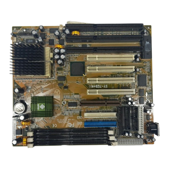
Motherboard Features SY-7IZB+N SY-7IZB+N MOTHERBOARD LAYOUT USB1 PS/2 Mouse Connector JP10 Connector Flash BIOS Winbond 83977 ATX Power AT Power COM 1 COM 2 JP44 PRT 1 AGP Slot PCI Slot #4 PCI Slot #2 PCI Slot #3 PCI Slot #1... -
Page 5: Chapter 1 Introduction
The SY-7IZB+N AGP/PCI Motherboard is a high-performance ® Celeron processor supported Baby AT form-factor system board. SY-7IZB+N uses the 440 ZX Chipset technology and supports Socket 370 Celeron processors. This Motherboard is fully compatible with industry standards and adds many technical enhancements. - Page 6 Introduction SY-7IZB+N SY-7IZB+N PLATFORM FEATURES Board Size 4-layer PCB, 26 x 22cm(”10.24x8.7”), Baby-AT Form Factor Socket 370 66/100MHz FSB Celeron Processor 300A/333/366/400/433/466/500/533 Built-in full speed 128KB L2 cache. Features Auto-detection of CPU voltage Chipset 440 ZX AGP Set ATX Power...
- Page 7 Introduction SY-7IZB+N Keylock 5-pin KeyLock Header Reset 2-pin Reset Switch Header Speaker 4-pin PC Speaker Header TB_LED 2-pin ACPI LED Header HDD_LED 2-pin IDE Device LED Header PWRBT ATX Power On/Off Switch 2-pin Header CMOS Clear Jumper AGP operating speed Select Jumper...
-
Page 8: Handling The Motherboard
Introduction SY-7IZB+N 1-2 HANDLING THE MOTHERBOARD To avoid damage to your Motherboard, follow these simple rules while unpacking: Before handling the Motherboard, ground yourself by grasping an unpainted portion of the system's metal chassis. Remove the Motherboard from its anti-static packaging. Hold the Motherboard by the edges and avoid touching its components. -
Page 9: Chapter 2 Hardware Setup
Hardware Setup SY-7IZB+N Chapter 2 HARDWARE SETUP Congratulations on your purchase of SY-7IZB+N Motherboard. You are about to install and connect your new Motherboard. Note: Do not unpack the Motherboard from its protective anti-static packaging until you have made the following preparations. -
Page 10: Unpacking The Motherboard
Hardware Setup SY-7IZB+N UNPACKING THE MOTHERBOARD When unpacking the Motherboard, check for the following items: The SY-7IZB+N 440 ZX AGP/PCI Motherboard This Quick Start Guide * The Installation CD-ROM * One IDE Device Flat Cable One Floppy Disk Drive Flat Cable... -
Page 11: Installation Guide
Hardware Setup SY-7IZB+N 2-3 INSTALLATION GUIDE We will now begin the installation of the Motherboard. Please follow the step-by-step procedure designed to lead you to a complete and correct installation. Warning: Turn off the power to the Motherboard, system chassis, and peripheral devices before performing any work on the Motherboard or system. - Page 12 Hardware Setup SY-7IZB+N Follow these steps to install the CPU in the Socket 370: Lift the socket handle up to a vertical position. Align the blunt edge of the CPU with the matching pinhole distinctive edge on the socket. Seat the processor in the socket completely and without forcing.
- Page 13 Hardware Setup SY-7IZB+N 2-3.3 SDRAM Memory Module Installation DIMM1 DIMM2 DIMM3 This Motherboard features 3 x DIMM for 168-pin 3.3V unbuffered DIMM modules, providing support for up to 256MB of main memory using DIMM modules from 8MB to 128MB. Number of...
- Page 14 Hardware Setup SY-7IZB+N 2-3.4 IDE Device Installation (HDD, CD-ROM) This Motherboard offers two primary and secondary IDE device connectors (IDE1, IDE2). It can support up to four high-speed HDD or CD-ROM. Connect one side of the 40-pin flat cable to the IDE device (HDD or...
- Page 15 Hardware Setup SY-7IZB+N 2-3.6 Front Panel Connections Power Keylock ACPI Speaker Plug the computer case's front panel devices to the corresponding headers on the Motherboard. 1. Power LED & KeyLock Plug the Power LED cable into the 5-pin Keylock header.
- Page 16 Hardware Setup SY-7IZB+N 3. Speaker Attach the 4-pin PC speaker cable from the case to the Speaker header on the Motherboard. 4. ACPI LED Connecting the 2-pin ACPI LED cable to the corresponding ACPI LED header will cause the LED to light whenever the system is in ACPI mode.
- Page 17 Hardware Setup SY-7IZB+N 2-3.7 External Peripherals Connections External devices such as the keyboard, printer, PS/2 mouse, modem, USB can be connected to the Motherboard. Normally, you can not plug your devices directly onto the Motherboard, except for the keyboard that plugs directly into the back panel KB connector.
- Page 18 Hardware Setup SY-7IZB+N 1. Serial Ports COM1/COM2 External Devices that use the COM ports include serial mice and modems. The COM port connectors are located on 2 separate brackets panels, as shown on the figure below. Please plug their respective 10 pin flat cable connectors into the COM1 and COM 2 serial port connectors on the Motherboard.
- Page 19 Hardware Setup SY-7IZB+N Parallel Port PRT1 This parallel port is used to connect the printer or other parallel devices. Your Motherboard comes with one 25-pin female external parallel connector with 25-pin flat cable. Plug the 25-pin end of the flat cable into the PRT1 parallel...
- Page 20 Hardware Setup SY-7IZB+N PS/2 Mouse Attach the mouse cable to the 6-pin male PS/2 mouse connector on the Motherboard to enable PS/2 mouse function. USB1 PS/2 Mouse Connector Connector AT Power COM 1 COM 2 PRT 1 Universal Serial Bus (USB) This Motherboard provides a dual-row 10-pin header (one pin is empty) to support two USB ports for your additional devices.
- Page 21 Hardware Setup SY-7IZB+N 2-3.8 Other Connections 1. Wake-On-LAN (WOL) Attach the 3-pin connector from the LAN card which supports the Wake-On-LAN (WOL) function to the JP44 header on the Motherboard. This WOL function lets users wake up the connected computer through the LAN card.
- Page 22 Hardware Setup SY-7IZB+N 2-3.9 Cooling Fan Installation 1. CPU Cooling Fan After you have seated the CPU properly on the processor, attach the 3-pin fan cable to the CPUFAN connector on the Motherboard. The fan will stop when the system enters into Suspend Mode.
- Page 23 Hardware Setup SY-7IZB+N 2-3.10 AGP VGA Card Insert the AGP VGA card into the AGP slot. Then connect the monitor information cable to the AGP card back plane external connector. Follow the manufacturer's instructions to perform the AGP VGA drivers installation.
- Page 24 Hardware Setup SY-7IZB+N Warning: Follow these precautions to preserve your Motherboard from any remnant currents when connecting to ATX power supply: Turn off the power supply and unplug the power cord of the ATX power supply before connecting to ATX PW connector.
- Page 25 Hardware Setup SY-7IZB+N 2-3.14 CMOS Clearing (JP5) In some cases the CMOS memory may contain wrong data, follow the steps below to clear CMOS memory. Clear the CMOS memory by momentarily shorting pin 2-3 on jumper JP5. This jumper can be easily identified by its white colored cap.
- Page 26 Hardware Setup SY-7IZB+N 2-3.16 Power-On by Keyboard Jumper (JP10) You can choose to enable the Power-On by Keyboard or Mouse function by shorting pin 1-2 on jumper JP1, otherwise, short pin 2-3 to disable this function. Support Power-On Enable Disable...
-
Page 27: Quick Bios Setup
This Motherboard does not use any hardware jumpers to set the CPU frequency. Instead, CPU settings are software configurable with the BIOS [SOYO COMBO SETUP]. The [SOYO COMBO SETUP] menu combines the main parameters that you need to configure, all in one menu, for a quick setup in BIOS. - Page 28 Move the cursor to the [CPU Frequency] field to set the CPU frequency, as shown in the following display. Available [CPU Frequency] settings on your SY-7IZB+N Motherboard are detailed in the following table. You are then required to fill in the next two consecutive fields: (1) the CPU Host/PCI Clock, and (2) the CPU Frequency.
-
Page 29: Troubleshooting At First Start
2-3.19 Troubleshooting at First Start Video (no display) related issues I built a new computer system using a Soyo board and nothing happens when turning it on, no video and no beeps from the PC speaker. What is happening and how can it be fixed? No screen and no beeps mean that your CPU and motherboard do not work at all. -
Page 30: Bios Issues
5EH_2CA1 (meaning revision 2CA1 for the SY-5EH board) or 6BA+ IV_2AA2 which means SY-6BA+ IV motherboard with 2AA2 bios. Where can I find the latest BIOS of my motherboard? Please go to the technical support page of one of the SOYO websites www.soyo.com.tw (Taiwan: ), and look up your motherboard to find the latest BIOS revision. -
Page 31: Modem Issues
Why? If you are sure that the modem driver has been installed correctly, then you need to install the south bridge driver from the SOYO CD, this is because Windows does not properly recognize relatively new chipsets. - Page 32 Then put back the peripherals one by one to identify which one causes the lockup. I can not get my board to run properly. Please make sure you have the latest bios and driver from the SOYO web site at: http://www.soyo.com 2-3.20 Power Off...
-
Page 33: Chapter 3 Bios Setup Utility
2. After the diagnostic checks, press the [Del] key to enter the Award BIOS Setup Utility. ROM PCI/ISA BIOS CMOS SETUP UTILITY AWARD SOFTWARE, INC. SOYO COMBO SETUP INTEGRATED PERIPHERALS STANDARD CMOS SETUP SUPERVISOR PASSWORD BIOS FEATURES SETUP USER PASSWORD... -
Page 34: Save And Exit Setup
BIOS Setup Utility SY-7IZB+N Hot Keys: Function keys give you access to a group of commands throughout the BIOS utility. Function Command Description Help Gives the list of options available for each item. Shift F2 Color Change the color of the display window. -
Page 35: Soyo Combo Setup
<DEL> key during the system diagnostic checks to enter the Award BIOS Setup program. The CMOS SETUP UTILITY will display on screen. Then, select the [SOYO COMBO SETUP] option from the main menu and press the <Enter> key. - Page 36 BIOS Setup Utility SY-7IZB+N 3-1.1 Quick CPU Frequency Setup Quick CPU Setting Description Frequency Setup Select the host clock of your 66/33 MHz 105/35 MHz Host/PCI Celeron processor from 75/37 MHz 110/36 MHz Clock these values. 83/41 MHz 115/38 MHz...
- Page 37 BIOS Setup Utility SY-7IZB+N 3-1.3 System Boot Control Settings System Boot Setting Description Note Control Settings Boot Sequence A, C, SCSI Choose the boot sequence adapted to C, A, SCSI your needs, for example: C, CD-ROM, A [A, C, SCSI] means...
- Page 38 BIOS Setup Utility SY-7IZB+N 3-1.4 CPU Device Monitoring CPU Device Setting Description Note Monitoring CPU Warning Disabled Default Temperature Enabled Set CPU temperature from 50°C to 70°C. The CPU will slow down when CPU temperature goes beyond the preset value. The CPU...
-
Page 39: Standard Cmos Setup
BIOS Setup Utility SY-7IZB+N 3-2 STANDARD CMOS SETUP Select the [STANDARD CMOS SETUP] option from the Main Menu and press [Enter] key. ROM PCI/ISA BIOS STANDARD CMOS SETUP AWARD SOFTWARE, INC. Date (mm:dd:yy) : Thu, Jan 1 1998 Time (hh:mm:ss) - Page 40 BIOS Setup Utility SY-7IZB+N 3-2.2 Hard Disks Type & Mode Choose the type and mode for the hard disks that you have already installed. Primary Setting Description Note (Secondary) Master & Slave Type Auto BIOS detects hard disk type Default automatically.
- Page 41 BIOS Setup Utility SY-7IZB+N 3-2.4 Video Select the video mode: EGA/VGA (Default), CGA 40, CGA 80, Mono (Monochrome). 3-2.5 Halt On When the BIOS detects system errors, this function will stop the system. Select which type of error will cause the system halt: All Errors (Default), No Errors, All But Diskette, All But Keyboard, All But Disk/Key.
-
Page 42: Bios Features Setup
BIOS Setup Utility SY-7IZB+N 3-3 BIOS FEATURES SETUP Select the [BIOS FEATURES SETUP] option from the Main Menu and press [Enter] key. ROM PCI/ISA BIOS BIOS FEATURES SETUP AWARD SOFTWARE, INC. Anti-Virus Protection : Enabled Assign IRQ For VGA : Enabled... - Page 43 BIOS Setup Utility SY-7IZB+N 3-3.1 Virus Warning Setting Description Note Anti - Virus Disabled Protection Enabled If set to enabled, the Default Paragon Anti-Virus. Function will scan your boot drive for boot virusses. If a boot virus is detected, the BIOS will display a warning message.
- Page 44 BIOS Setup Utility SY-7IZB+N 3-3.4 Security Option Use this feature to prevent unauthorized system boot-up or use of BIOS Setup. The following table describes the security settings. Setting Description Security Option System Each time the system is booted, the password prompt appears.
- Page 45 BIOS Setup Utility SY-7IZB+N Typematic Settings (Continued) Typematic Setting Description Note Settings The following [Typematic Rate] and [Typematic Delay] fields are active only if [Typematic Rate Setting] is set to [Enabled] Typematic Rate 6 (Char/sec) Choose the rate at which...
-
Page 46: Chipset Features Setup
BIOS Setup Utility SY-7IZB+N 3-4 CHIPSET FEATURES SETUP Caution: Change these settings only if you are already familiar with the Chipset. ROM PCI/ISA BIOS CMOS SETUP UTILITY CHIPSET FEATURES SETUP Auto Configuration : Enabled Passive Release : Enabled SDRAM Precharge Control... -
Page 47: Auto Configuration
BIOS Setup Utility SY-7IZB+N 3-4.1 CHIPSET FEATURES SETUP CHIPSET Setting Description Note FEATURES Auto Disabled Configuration Enabled It is strongly recommended Default to enable this option so that the system automatically sets all chipset feature options on the left panel of the screen (except for cache update &... - Page 48 BIOS Setup Utility SY-7IZB+N CHIPSET FEATURES SETUP (Continued) CHIPSET Setting Description Note FEATURES 16 BIT I/O Use the default setting Default Recovery Time Memory Hole At Disabled Default 15M-16M Enabled Some interface cards will map their ROM address to this area. If this occurs, select [Enabled] in this field.
-
Page 49: Power Management Setup
BIOS Setup Utility SY-7IZB+N 3-5 POWER MANAGEMENT SETUP The [POWER MANAGEMENT SETUP] sets the system's power saving functions. ROM PCI/ISA BIOS POWER MANAGEMENT SETUP AWARD SOFTWARE, INC. ACPI function : Enabled ** Reload Global Timer Events ** PM Control by APM... - Page 50 BIOS Setup Utility SY-7IZB+N 3-5.1 Power Management Controls Power Setting Description Note Management Controls ACPI Disabled Default function Enabled ACPI (Advanced Configuration Power Management Interface) PM Control To use Advanced Power Default by APM Management (APM) you must run [power.exe] under DOS V6.0 or later version.
- Page 51 BIOS Setup Utility SY-7IZB+N 3-5.2 PM Timers PM Timers Setting Description Note Power User Define Lets you define the HDD Default Management and system power down times. Disable Disables the Green PC Features. Doze Standby Suspend timer timer timer power down...
- Page 52 BIOS Setup Utility SY-7IZB+N Down 1-15Min When the set time has Some older model HDDs elapsed, BIOS sends a may not support command to the HDD to this advanced power down. This turns off function. the HDD motor. 3-5.3 PM Events...
-
Page 53: Pnp/Pci Configuration Setup
BIOS Setup Utility SY-7IZB+N 3-6 PNP/PCI CONFIGURATION SETUP This option sets the Motherboard's PCI Slots. ROM PCI/ISA BIOS PNP/PCI CONFIGURATION AWARD SOFTWARE, INC. Resources Controlled By : Manual Slot 1/AGP Use IRQ No. : Auto Reset Configuration Data : Disabled Slot 2 Use IRQ No. - Page 54 BIOS Setup Utility SY-7IZB+N 3-6.1 PNP/PCI Configuration Controls PNP/PCI Setting Description Note Controls Resources Manual BIOS does not manage PCI/ISA Controlled By PnP card IRQ assignment. Requires to assign IRQ-# and DMA-# to PCI or ISA PnP manually. IRQ-3,4,5,7,9,10,11,12,14,15 assigned to: _...
- Page 55 BIOS Setup Utility SY-7IZB+N PNP/PCI Configuration Setup (Continued) PNP/PCI Setting Description Note Setup Interrupt How to set the BIOS to release the IRQ to the PnP Interrupt pool: Line PnP / PCI configuration Integrated Peripherals IRQ 15 IRQ 15: PCI / ISA PnP On-Chip Secondary PCI IDE: disabled...
-
Page 56: Load Setup Defaults
This option is recommended if you need to reset the system setup and to retrieve the old values. ROM PCI/ISA BIOS CMOS SETUP UTILITY AWARD SOFTWARE, INC. SOYO COMBO SETUP INTEGRATED PERIPHERALS STANDARD CMOS SETUP SUPERVISOR PASSWORD BIOS FEATURES SETUP USER PASSWORD... -
Page 57: Integrated Peripherals
BIOS Setup Utility SY-7IZB+N 3-8 INTEGRATED PERIPHERALS Caution: Change these settings only if you are already familiar with the Chipset. The [INTEGRATED PERIPHERALS] option changes the values of the chipset registers. These registers control the system options in the computer. - Page 58 BIOS Setup Utility SY-7IZB+N 3-8.1 IDE Device Controls IDE Controls Setting Description Note IDE HDD Block Mode Disabled Enabled Invokes multi-sector Default transfer instead of one sector per transfer. Not all HDDs support this function. mode 0-4 0 is the slowest speed...
- Page 59 BIOS Setup Utility SY-7IZB+N 3-8.4 FDC Controls FDC Controls Setting Description Note Onboard FDC Disabled Turn off the on-board controller floppy controller Enabled Use the on-board Default floppy controller 3-8.5 Onboard Serial Ports Onboard Serial Setting Description Note Ports Onboard...
- Page 60 BIOS Setup Utility SY-7IZB+N Onboard Parallel Ports (Continued) Onboard Parallel Setting Description Note Ports Parallel Port Mode ECP/EPP The mode depends on Default your external device that connects to this port. EPP/SPP If [Parallel Port Mode] is set to [ECP] mode...
-
Page 61: Supervisor Password
BIOS Setup Utility SY-7IZB+N 3-8.7 MULTI I/O ADDRESSES Default settings for multi-I/O addresses are as follows: Port I/O Address Status LPT1 378H ECP/EPP COM1 3F8H COM2 2F8H Warning: If a default I/O address conflicts with other I/O cards such as sound card, you must change one of the I/O addresses to remedy to this address conflict. - Page 62 BIOS Setup Utility SY-7IZB+N Choose [SUPERVISOR PASSWORD] from the Main Menu [Enter] and press . The following prompt appear: Enter Password: Warning: If you forget or lose the password, the only way to access the system is to set jumper JP5 to clear the CMOS RAM.
-
Page 63: User Password
BIOS Setup Utility SY-7IZB+N This diagram outlines the password selection procedure: Type the Password Press <Enter> without Type the Password ↔ ROM PCI/ISA BIOS Press: and Press: <Enter> entering the password ↔ CMOS SETUP UTILITY Press: Without entering password AWARD SOFTWARE, INC. -
Page 64: Ide Hdd Auto Detection
BIOS Setup Utility SY-7IZB+N 3-11 IDE HDD AUTO DETECTION This Main Menu function automatically detects the hard disk type and configures the STANDARD CMOS SETUP accordingly. ROM PCI/ISA BIOS CMOS SETUP UTILITY AWARD SOFTWARE, INC. HARD DISKS TYPE SIZE CYLS... -
Page 65: Chapter 4 Drivers Installation
Operating System other than Windows 2000 or NT. Your SY-7IZB+N Motherboard comes with a CD-ROM labeled "SOYO CD." The SOYO CD contains (1) the user's manual file for your new Motherboard, (2) the drivers software available for installation, and (3) a database in HTML format with information on SOYO Motherboards and other products. - Page 66 SOYO Motherboard you own and displays the corresponding model name. The user's manual files included on the SOYO CD are in PDF (Postscript Document) format. In order to read a PDF file, the appropriate Acrobat Reader software must be installed in your system.
- Page 67 Driver Installation SY-7IZB+N Step 2. Install Drivers and Utilities Click the Install Drivers button to display the list of drivers software that can be installed with your Motherboard. The Start Up program displays the drivers available for the particular model of Motherboard you own.
- Page 68 Step 3. Check the Latest Releases Click the 'Check the latest Releases' button to go the SOYO Website to automatically find the latest BIOS, manual and driver releases for your motherboard. This button will only work if your computer is connected to the internet through a network or modem connection.
Need help?
Do you have a question about the SY-7IZB+N and is the answer not in the manual?
Questions and answers