Table of Contents
Advertisement
Available languages
Available languages
MICROWAVE HOOD COMBINATION
INSTALLATION INSTRUCTIONS
This product is suitable for use above electric or gas cooking products up to 36" (91.4 cm) wide.
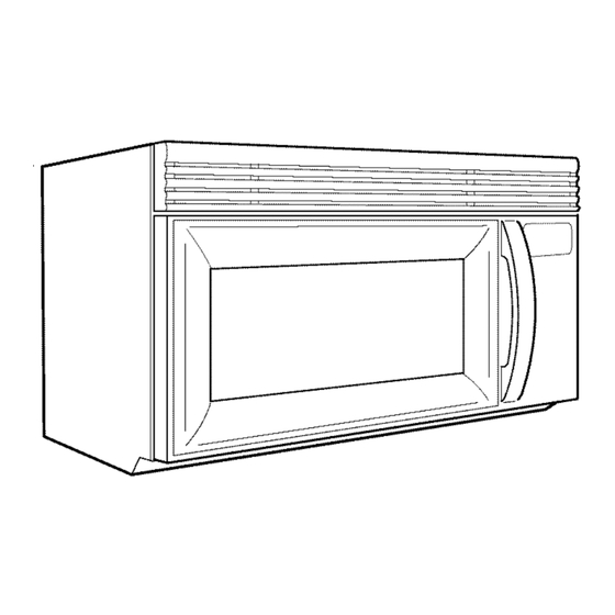
These installation instructions cover different models. The appearance of your particular model may differ slightly from the
illustration in these installation instructions.
COMBINAClON
MICROONDAS CAMPANA
INSTRUCClONES DE INSTALAClON
Este producto puede usarse encima de productos para cocci6n el6ctricos o a gas de 36" (91,4 cm) de ancho o menor.
Estas instrucciones de instalaci6n cubren diferentes modelos. La apariecia de su modelo en particular puede ser
ligeramente diferente de la ilustraci6n en estas instrucciones de instalaci6n.
TableofContents / [ndice
OVEN SAFETY ...................................................
2
.....................................
2
...........................................
3
Tools and Parts .......................................................................
3
Location Requirements
..........................................................
4
Product Dimensions ...............................................................
4
Electrical Requirements ..........................................................
5
.............................................
5
Remove Mounting Plate .........................................................
5
Rotate Air Deflector ................................................................
5
Locate Wall Stud(s) .................................................................
7
Mark Rear Wall .......................................................................
8
Drill Holes in Rear Wall ...........................................................
8
Attach Mounting Plate to Wall ................................................
9
Prepare Upper Cabinet ...........................................................
9
Install Damper Assembly ......................................................
10
Install the Microwave Oven ..................................................
10
Complete Installation ............................................................
12
...........................................................................
12
Replacement
Parts ...............................................................
12
Accessories ...........................................................................
12
CAMPANA...13
...... 13
REQUISITOS
DE INSTALACION .........................................................
15
Piezas y herramientas ........................................................................
15
Requisitos de ubicaci6n .....................................................................
15
Deminsiones del producto .................................................................
16
Requisitos el_ctricos ..........................................................................
17
Retire la placa de montaje .................................................................
17
Rote el desviador de aire ...................................................................
17
Ubique el(los) pie(s) derecho(s) de pared ..........................................
Marque la pared posterior .................................................................
20
Taladrar oriticios en la pared posterior ..............................................
20
Ajuste la placa de montaje a la pared ...............................................
21
Preparaci6n del gabinete superior .....................................................
22
Instale el ensamblaje de la compuerta de tiro ................................... 22
Instalaci6n del homo de microondas ................................................
22
Complete la instalaci6n ......................................................................
24
ASISTENCIA ..........................................................................................
24
Refacciones .......................................................................................
24
Accesorios ..........................................................................................
24
IMPORTANT: Read Installation Instructions thoroughly before beginning installation. Save Installation Instructions for local house
inspector's use.
IMPORTANTE:
Lea las instrucciones de instalaci6n a fondo antes de cornenzar la instalaci6n. Guarde las instrucciones para el uso del
inspector local de la casa.
8205139
Advertisement
Table of Contents

Related Manuals for KitchenAid KHHS179LWH5


Summary of Contents for KitchenAid KHHS179LWH5
-
Page 1: Table Of Contents
MICROWAVE HOOD COMBINATION INSTALLATION INSTRUCTIONS This product is suitable for use above electric or gas cooking products up to 36" (91.4 cm) wide. These installation instructions cover different models. The appearance of your particular model may differ slightly from the illustration in these installation instructions. -
Page 2: Microwave Oven Safety
MICROWAVE OVEN SAFETY Your safety and the safety of others are very important. We have provided many important safety messages in this manual and on your appliance. Always read and obey all safety messages. This is the safety alert symbol. This symbol alerts you to potential hazards that can kill or hurt you and others. -
Page 3: Installation Requirements
Rectangular to Round Transition 31/4 '' x 10" (8.3 x 25.4 cm) vent system = 73ft (22.2 m) total NOTE: The minimum 3" (7.6 cm) clearance must exist between the top of the microwave oven and the rectangular to round transition piece so that the damper can open freely and fully. -
Page 4: Electrical Requirements
Parts Supplied Special Requirements For reorder information, see "Replacement Parts" section. NOTE: The hardware items listed here are for wood studs. For For Wall Venting Installation Only: other types of wall structures, be sure to use appropriate fasteners. • The 12" x 4" (30.5 x 10.2 cm) cutout area must align with the rectangular hole in the mounting plate. -
Page 5: Installationinstructions
GROUNDING iNSTRUCTiONS [] For all cord connected appliances: The microwave oven must be grounded. In the event of an electrical short circuit, grounding reduces the risk of electric shock by providing an escape wire for the electric current. The microwave oven is equipped with a cord having a grounding wire with a grounding plug. -
Page 6: Rotate Air Deflector
3. Slide airdeflector outofmicrowave oven. Roof Venting Installation Only 1. Repeat Step 1 from "Wall Venting Installation Only." 2. Repeat Step 2 from "Wall Venting Installation Only." 3. Repeat Step 3 from "Wall Venting Installation Only." 4. Rotate air deflector so that deflector feet face the bottom of the microwave oven, and the exhaust port (open end) of air deflector aligns with microwave oven exhaust port. - Page 7 bscc e Stud(s} NOTE: If no wall studs exist within the cabinet opening, do not 1. Using a stud finder, locate the edges of the wall stud(s) within install the microwave oven, the opening. See illustrations in "Possible Wall Stud Configurations," 2.
- Page 8 Wall Venting Installation Only The microwave oven must be installed on a minimum of 1 wall Centerline Upper Cabinet Bottom stud, preferably 2, using a minimum of 1 lag screw, preferably 2 or more. 1. Using measuring tape, find and clearly mark the vertical centerline of the opening.
-
Page 9: Locate Wall Stud(S)
Afi csch Moun One Wall Stud at Two Corner Holes (Figure 3) NOTE: Secure the mounting plate to the wall at all 4 corner holes 1. With the support tabs of the mounting plate facing forward, drilled into the wall studs and/or drywall using either 1/4-20 x 3" insert 1/4-20 x 3"... - Page 10 5. Cut the 11/2"(3.8 cm) diameter hole at the circular shaded area "G" on the template. This hole is for the power supply cord. ! sto!! tse Mic eve Oven NOTE: If upper cabinet is metal, the supply cord bushing needs to be installed around the supply cord hole, as shown.
- Page 11 If adjustment is required, rotate microwave oven downward. Using 2 or more people, lift microwave oven off of mounting For Roof Venting Installation Only plate, and set aside on a protected surface. 1. Insert damper assembly through the cabinet cutout so that the long tab of the damper assembly slides under the raised tabs of the damper plate.
-
Page 12: Assistance
ASSISTANCE Comple st<sllcAion Refer to the Use and Care Guide for instructions on how to install filters into your model. Call your authorized dealer or service center. When you call, you will need the microwave oven model number and serial number. Both numbers can be found on the model and serial number plate, which is located behind the microwave oven door on the front frame of the microwave oven. -
Page 13: Seguridad De La Combinacion Microondas Campana
SEGURIDAD DE LA COMBINACION MICROONDAS CAMPANA Su seguridad y la seguridad de los demas es muy importante. Hemos incluido muchos mensajes importantes de seguridad en este manual yen su electrodomestico. Lea y obedezca siempre todos los mensajes de seguridad. Este sfmbolo le llama la atencion sobre peligros potenciales que pueden ocasionar la muerte o una lesion a usted y a los demas. - Page 14 Tubo de ajuste rectangular a redondo Largo recomendado del ducto de escape NOTA: Debe haber un espacio minimo de 3" (7,6 cm) entre la parte superior del homo de microondas y el tubo de ajuste Debera usarse un ducto de escape rectangular de 31/4"x 10" rectangular a redondo para poder abrir la compuerta libre y (8,3 x 25,4 cm) o un ducto de escape redondo de 6"...
- Page 15 REQUlSlTOSDE INSTALACION Materiales necesarios Accesorios corrientes para la ventilaci6n a trav_s de la pared o del techo. Vea la secci6n "Especificaciones para el dise_o de la ventilaci6n'. Herramientas necesarias ReQna las herramientas y piezas necesarias antes de comenzar la Reqf stos #_2®...
-
Page 16: Requisitos El_Ctricos
Dimensiones de instalacibn NOTA: El contacto de pared de conexi6n a tierra de 3 terminaies debe estar dentro del gabinete superior. Vea la seccidn "Requisites electricos". Peligro de Choque Electrico Conecte a un contacto de pared de conexion a tierra de 3 terminalee. -
Page 17: Instrucciones De Instalaci
INSTRUCCIONESDE INSTALACION 2. Mantenga juntos la placa de la compuerta de tiro y el tornillo y dejelos a un lado. de n otGe 3. Deslice el desviador de aire fuera del homo de microondas. Saque el contenido restante de la cavidad del homo de microondas. - Page 18 Deslice el desviador de aire dentro de la parte posterior del Rote el desviador de aire de manera que las patas del homo de microondas, como se muestra, cerciorandose desviador queden mirando la base del homo de microondas y que la lumbrera de escape (extreme abierto) este alineada con la lumbrera de escape (extreme abierto) del desviador de aire la lumbrera de escape del homo de microondas.
- Page 19 NOTA: Si no hay pies derechos de pared dentro de ia abertura del 1, Ubique los extremes del(de los) pie@) derecho(s) de pared gabinete, no instale el homo de microondas. dentro de la abertura con un detector de pies derechos. Vea las ilustraciones en "Posibles configuraciones de los pies 2.
-
Page 20: Ubique El(Los) Pie(S) Derecho(S) De Pared
Solamente para la instalacibn con ventilacibn en la pared El homo de microondas debera instalarse como mJnimo sobre 1 pie derecho de pared, preferentemente 2, usanclo un m[nimo de 1 tirafondo, preferentemente 2 o mas. Con la cinta de mediB ubique y marque claramente la linea central vertical de la abertura. - Page 21 Empuje los 4 pernos con las tuercas de ajuste a traves del panel de yeso y apriete los pernos con los dedos para Instalacibn para pies derechos de pared en los cuatro asegurarse que las tuercas de ajuste se hayan abierto contra oriflcios de esquina (flgura 4) el panel de yeso.
- Page 22 Pies derechos de pared en los cuatro orificios de Solamente para la instalacibn con ventilacibn en el techo esquina (figura 4) 7. Corte un orificio de 3/4" (19 mm) en una esquina del Area "F" 1. Posicione la placa de montaje en la pared, asegurandose de rectangular sombreada en la plantilla superior del gabinete.
- Page 23 NOTAS: 3. Con la ayuda de 2 o mas personas, levante el homo de microondas y cuelguelo de las lengQetas de soporte en la • AIgunos gabinetes superiores pueden necesitar pernos mas parte inferior de la placa de montaje. largos o mas cortos que 3" (7,6 cm). Los pernos mas largos o NOTA: No tome o use la puerta o la manija de la puerta durante la mas cortes estan disponibles en la mayoria de las ferreterias.
- Page 24 Conecte el ducto de escape al ensamblaje de la compuerta de tiro. ASlSTENCIA Llame a su distribuidor autorizado o centro de servicio. Cuando Ilame, usted necesitara tener a mano el nQmero del modelo y de la serie del homo de microondas. Se pueden encontrar ambos nQmeros en la placa con el nQmero de modelo y de serie, que se encuentra detras de en la puerta del homo de microondas en el...
Need help?
Do you have a question about the KHHS179LWH5 and is the answer not in the manual?
Questions and answers