Trane YSC036E Owner's Manual
Packaged rooftop air conditioners precedent - gas/electric 3-10tons-60hz
Hide thumbs
Also See for YSC036E:
- Installation, operation and maintenance manual (68 pages) ,
- Installation & operation manual (72 pages) ,
- Installation, operation and maintenance manual (64 pages)
Advertisement
Quick Links
Owner Manual
Packaged Rooftop Air Conditioners
Precedent™- Gas/Electric
3 - 10 Tons - 60 Hz
Model Number:
YSC036E - YSC060E
YHC036E - YHC072E
YSC072F - YSC120F
YHC120E
YHC048F - YHC060F
YHC072F - YHC102F
SAFETY WARNING
Only qualified personnel should install and service the equipment.The
installation, starting up, and servicing of heating, ventilating, and air-
conditioning equipment can be hazardous and requires specific
knowledge and training. Improperly installed, adjusted or altered
equipment by an unqualified person could result in death or serious injury.
When working on the equipment, observe all precautions in the literature
and on the tags, stickers, and labels that are attached to the equipment.
May 2013
RT-SVU03H-EN
© 2013Trane
All rights reserved
4
Thermostat
Room thermostats are delicate temperature sensing controls.Their main
function is to energize and de-energize the heating or cooling circuit to
maintain the temperature setting you select.
Many thermostats contain a room thermometer to indicate the approximate
room temperature and a temperature scale at the adjustment indicator to
select the desired indoor air temperature. In addition, most thermostats
have a selector mode switch with Heat, Off and Cool positions and a fan
switch with On and Off positions.
When the switch is positioned at Off your unit will not operate in either the
heat or cool modes. If the selector switch is set at Heat the unit will
automatically cycle on and off to maintain the desired temperature setting.
The unit will also operate automatically when the selector switch is
positioned at Cool.
The fan selector switch can be used to operate the indoor fan continuously
by positioning it at On. When set to Auto the fan will only operate when
required during the heating or cooling cycles.
To ensure that the thermostat operates properly, it must be level and
positioned to avoid the influence of such external heat sources as lamps,
televisions or other heat producing appliances.
1
Cautions, Warnings and Notices
WARNING
Indicates a potentially hazardous situation which, if not avoided, could
result in death or serious injury
CAUTION
Indicates a potentially hazardous situation which, if not avoided, could
result in minor or moderate injury. It may also be used to alert against
unsafe practices.
NOTICE
Indicates a situation that could result in equipment or property-damage
only accidents.
Important: Environmental Concerns! Scientific research has shown
that certain man-made chemicals can affect the earth's naturally occurring
stratospheric ozone layer when released to the atmosphere. In particular,
several of the identified chemicals that may affect the ozone layer are
refrigerants that contain Chlorine, Fluorine and Carbon (CFCs) and those
containing Hydrogen, Chlorine, Fluorine and Carbon (HCFCs). Not all
refrigerants containing these compounds have the same potential impact
to the environment.Trane advocates the responsible handling of all
refrigerants-including industry replacements for CFCs such as HCFCs and
HFCs.
Important: Responsible Refrigerant Practices!Trane believes that
responsible refrigerant practices are important to the environment, our
customers, and the air conditioning industry. All technicians who handle
refrigerants must be certified.The Federal Clean Air Act (Section 608) sets
forth the requirements for handling, reclaiming, recovering and recycling of
certain refrigerants and the equipment that is used in these service
procedures. In addition, some states or municipalities may have additional
requirements that must also be adhered to for responsible management of
refrigerants. Know the applicable laws and follow them.
5
Air Filters
Filters are to be used with this unit. Units ship from the factory with filters
installed.
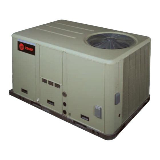
Figure 1.
Gas unit overview
RETURN AIR
SUPPLY AIR
PRESSURE SWITCH
GAS VALVE
COMPRESSOR
It is very important to keep the central duct system air filters clean. Be sure
to inspect them at least once each month when the system is in constant
operation. (In new homes, check the filters every week for the first 4 weeks.)
See
Table 1
for the required filter size(s).
If you have disposable type filters, replace them with new filters of the same
type and size. Do not attempt to clean disposable filters.
Permanent type filters can be cleaned by washing them with a mild
detergent and water. Ensure that the filters are thoroughly dry before
reinstalling them in the unit (or duct system).
It may be necessary to replace permanent filters annually if washing fails to
clean the filter, be sure to use the same type and size as was originally
2
General Information
Important: Remember the following instructions at all times.
WARNING
Hazard of Explosion or Fire!
Do not store or use gasoline or other flammable vapors and liquids in the
vicinity of this or any other appliance.
IFYOU SMELL GAS, follow instructions below:
• Do not try to light any appliance.
• Do not touch any electrical switch.
• Do not use any phone in your building.
• Open windows and doors.
• Alert others and evacuate building immediately.
• From a phone outside of the building, immediately call your gas
supplier. Follow the gas supplier's instructions. If you can not reach
your gas supplier, call the fire department.
Failure to follow recommendations listed above could result in death or
serious injury and equipment or property damage.
WARNING
Safety Hazards!
• Do not use this furnace if any portion has been under water as it may
have rendered the unit hazardous to operate. Immediately call a
qualified service technician to inspect the furnace and to replace any
part or the control system and any gas control which has been under
water.
• Should overheating occur, or the unit gas valve fail to shut off, close
the gas valve to the furnace before shutting off the electrical supply.
Failure to follow recommendations could result in death, serious injury
and equipment or property damage.
6
installed.
Table 1.
Recommended standard filters
Unit Model Number
Filter Size
Inches
Millimeters
YH/SC036E*, YHC037E*
(2) 20x30x2
(2) 508x762x50
YSC048E*
(2) 20x30x2
(2) 508x762x50
YSC060E*
(2) 20x30x2
(2) 508x762x50
YHC047E*, YHC048*
(4) 16x25x2
(4) 406x635x50
YHC060*, YHC067E*
(4) 16x25x2
(4) 406x635x50
YSC072F*
(4) 16x25x2
(4) 406x635x50
YSC090F*
(4) 16x25x2
(4) 406x635x50
YHC072F*
(4) 20x25x2
(4) 508x635x50
YSC092F*
(4) 20x25x2
(4) 508x635x50
YSC102F*
(4) 20x25x2
(4) 508x635x50
YSC120F*
(4) 20x25x2
(4) 508x635x50
YHC092F*
(4) 20x25x2
(4) 508x635x50
YHC102F*
(4) 20x25x2
(4) 508x635x50
YHC120E*
(2) 20x30x2
(2) 508x762x50
(3) 20x25x2
(3) 508x635x50
3
WARNING
Safety Hazards!
• Never perform any maintenance procedures until the electrical power
to the unit is turned off.
• Never perform any maintenance procedures until the gas valve is the
gas supply line is turned off.
• Never remove any panels from the unit while it is operating.
• Never remove panels or parts from the unit that are not discussed in
this manual.
• Never cover the unit since it is designed to operate year round.
Failure to follow recommendations could result in death or serious injury.
Your unit is of complex design.To ensure that it performs safely and gives
long lasting services, some of the maintenance work must be performed by
a qualified service person.
When a service person is referred to in this manual it is describing a service
technician who has had special training or a number of years experience in
servicing this type of equipment. It is your responsibility to select a qualified
service company that can provide a service person of this caliber.
7
Heating System
Heating Cycle Operation
Your unit's heating system has a solid-state electronic ignition control that
lights the furnace burners each time the thermostat calls for heat. At the end
of each heating cycle the furnace burners are extinguished.This type of
system is called Direct Spark Ignition (DSI).
A normal heating cycle begins when the air temperature drops below the
thermostat setting.The thermostat then energizes the heating electrical
circuit that starts and controls the furnace burners. Shortly after the burners
ignite the indoor fan starts and circulates warm air through the conditioned
space.
When the air temperature rises to the thermostat setting the thermostat de-
energizes the heating electrical circuit, which in turn extinguishes the
burners.The indoor fan continues to circulate warm air until most of the
heat is removed from the unit's combustion chamber.
Safety Controls
• Your unit is equipped with an automatic reset safety limit control to
prevent overheating. When this control opens, it shuts down the
heating electrical circuit until the unit cools down sufficiently.
Inadequate airflow (i.e., caused by dirty filters or defective fan motor)
may cause the unit to cycle on and off as the limit trips and automatically
resets. If you suspect that the unit is cycling on its limit control,
immediately contact a service person for instructions.
• If flames from the burner are not properly drawn into the heat
exchanger, a Flame Rollout Protection Control will open causing the
furnace to shut off.The cause must be investigated by a qualified
service person.
• If installed, the condensate overflow switch will shut down the unit
before a drain pan overflow occurs.
Advertisement

Subscribe to Our Youtube Channel
Related Manuals for Trane YSC036E


Summary of Contents for Trane YSC036E
- Page 1 Only qualified personnel should install and service the equipment.The Safety Hazards! to the environment.Trane advocates the responsible handling of all installation, starting up, and servicing of heating, ventilating, and air- • Do not use this furnace if any portion has been under water as it may...
- Page 2 For more information, visit www.IRCO.com. The manufacturer has a policy of continuous product and product data improvement and reserves the right to change design and specifications without notice. © 2013 Trane All rights reserved We are committed to using RT-SVU03H-EN 13 May 2013...
Need help?
Do you have a question about the YSC036E and is the answer not in the manual?
Questions and answers