Table of Contents
Advertisement
Installation, Operation,
and Maintenance
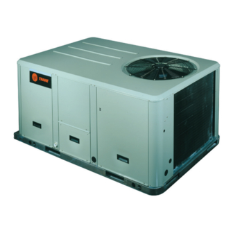
Packaged Rooftop Air Conditioners
Precedent™ — Gas/Electric
5 – 10Tons – 50 Hz
Model Numbers
Only qualified personnel should install and service the equipment. The installation, starting up, and
servicing of heating, ventilating, and air-conditioning equipment can be hazardous and requires specific
knowledge and training. Improperly installed, adjusted or altered equipment by an unqualified person could
result in death or serious injury. When working on the equipment, observe all precautions in the literature
and on the tags, stickers, and labels that are attached to the equipment.
September 2012
YSC060ED - YSC120ED
SAFETY WARNING
RT-SVX38B-EN
Advertisement
Table of Contents
Troubleshooting

Related Manuals for Trane YSC060ED


Summary of Contents for Trane YSC060ED
- Page 1 Precedent™ — Gas/Electric 5 – 10Tons – 50 Hz Model Numbers YSC060ED - YSC120ED SAFETY WARNING Only qualified personnel should install and service the equipment. The installation, starting up, and servicing of heating, ventilating, and air-conditioning equipment can be hazardous and requires specific knowledge and training.
-
Page 2: Important Environmental Concerns
Responsible Refrigerant Practices! • Updated Model Number Description, Maintenance, Troubleshooting Trane believes that responsible refrigerant practices are important to the environment, our customers, and the air conditioning industry. All technicians who handle refrigerants must be certified.The Federal Clean Air Act... -
Page 3: Table Of Contents
Table of Contents Model Number Description Zone Temperature Sensor (ZTS) Service Indi- ....4 cator ....... . .40 General Information . -
Page 4: Model Number Description
Options Economizer, Dry Bulb 0-100% Convertible with Barometric Relief No Communications Interface Digit 4,5,6 - Nominal Gross Economizer, Reference Enthalpy Trane Communications Interface 0-100% without Barometric Relief LonTalk® Communications Interface Cooling Capacity (MBh) Economizer, Reference Enthalpy Novar 2024 Controls 3Ton... -
Page 5: Model Number Notes
Model Number Description Clogged Filter Switch , Fan Failure horizontal configuration. 21. Available for 3, 4, 5, 6, 7½, 8½ ton Switch and Condensate Drain Pan Barometric Relief for horizontal standard/high efficiency models Overflow Switch configured units must be ordered only. -
Page 6: General Information
24 VAC. without first completing the start-up procedure detailed under “Unit Start-Up, ” p. RTCI - ReliaTel™ Trane Communication The manufacturer will not assume any responsibility for Interface (Optional) equipment damage resulting from condensate This module is used when the application calls for an accumulation on the unit’s electrical and/or mechanical... -
Page 7: Low Pressure Control
General Information RLCI - ReliaTel™ LonTalk® Communication pressure differential across the filters decreases to approximately 0.4" w.c.The clogged filter output is Interface (Optional) energized when the supply fan is operating and the This module is used when the application calls for an clogged filter switch has been closed for at least 2 minutes. -
Page 8: High Pressure Control
RTRM is powered up, i.e. after a power failure, the control timed override with override cancellation. It is used with a will default to the number one circuit compressor. Trane Integrated Comfort™ building management Zone Sensor Module (ZSM) (BAYSENS106*) system. -
Page 9: Evaporator Frost Control
General Information Auto fan settings. It is a manual or auto changeover control with dual setpoint capability. Other features include a timed override function, lockable system settings, and Fahrenheit or Celsius temperature display. Included with the wireless zone sensor will be a receiver that is to be mounted inside the unit, a mounting bracket, and a wire harness. -
Page 10: Unit Dimensions
These clearances are the minimum distances necessary to exhaust and economizer airflows, or recirculation of hot assure adequate serviceability, cataloged unit capacity, condenser air. and peak operating efficiency. Figure 1. Typical installation clearances for single & multiple unit applications YSC060ED YSC072-120ED RT-SVX38B-EN... - Page 11 Unit Dimensions Figure 2. 5 tons standard efficiency Notes: 1. All dimensions are in inches/millimeters. 2. ½ NPT Gas Connection Figure 3. 5 tons standard efficiency - roof curb Note: All dimensions are in inches/millimeters. 44 MM 44 MM 1038 1038 MM 1053 1053 MM...
- Page 12 Unit Dimensions Figure 4. 5 tons standard efficiency - unit clearance and roof opening Note: All dimensions are in inches/millimeters. CLEARANCE 36” (914 MM) Figure 5. 6, 7½ tons standard efficiency Note: All dimensions are in inches/millimeters. RT-SVX38B-EN...
- Page 13 Unit Dimensions Figure 6. 6, 7½ tons standard efficiency - roof curb Note: All dimensions are in inches/millimeters. (356 MM) (2130 MM) Figure 7. 6, 7½ tons standard efficiency - unit clearance and roof opening Note: All dimensions are in inches/millimeters. RT-SVX38B-EN...
- Page 14 Unit Dimensions Figure 8. 8½ - 10 tons standard efficiency Note: All dimensions are in inches/millimeters. 1/2 NPT GAS CONNECTION Figure 9. 8½ - 10 tons standard efficiency - roof curb Note: All dimensions are in inches/millimeters. (356 MM) (2130 MM) RT-SVX38B-EN...
- Page 15 Unit Dimensions Figure 10. 8½ - 10 tons standard efficiency - unit clearance and roof opening Note: All dimensions are in inches/millimeters. RT-SVX38B-EN...
-
Page 16: Installation
Installation Pre-Installation Procedure WARNING WARNING Fiberglass Wool! Heavy Objects! Product contains fiberglass wool. Disturbing the Ensure that all the lifting equipment used is properly insulation in this product during installation, rated for the weight of the unit being lifted. Each of the maintenance or repair will expose you to airborne cables (chains or slings), hooks, and shackles used to particles of glass wool fibers and ceramic fibers known... -
Page 17: Foundation
(a) Weights are approximate. (b) Corner weights are given for information only. Figure 12. Rigging and center of gravity (a),(b) Table 2. Factory installed options (fiops)/accessory net weights (lbs) YSC060ED YSC072E-120ED Net Weight Net Weight Accessory 5 Ton 6-10 Ton... -
Page 18: Ductwork
Installation For rooftop applications, ensure the roof is strong enough When attaching the ductwork to the unit, provide a water to support the combined unit and support structural tight flexible connector at the unit to prevent operating weight. Refer to Table 1, p. - Page 19 Installation Rigging WARNING Combustible Materials! WARNING Maintain proper clearance between the unit heat Heavy Objects! exchanger, vent surfaces and combustible materials. Ensure that all the lifting equipment used is properly Refer to unit nameplate and installation instructions for rated for the weight of the unit being lifted. Each of the proper clearances.
-
Page 20: General Unit Requirements
2 retaining clips on the duct flange. blower housing:YSC060ED*H,YSC072ED*H, Secure outward edge of the duct cover with two YSC090ED*H,YSC102ED*H,YSC120ED*H. screws. -
Page 21: Tco-1 Instructions
3 and go on to next step Supply Duct Cover in the installation process. Unit Model Number YSC060ED*H Figure 19. TCO1 location (YSC060ED*H) LOCATION OF TCO1 LIMIT LOCATION OF TCO1 LIMIT FOR THE Y(S/H)C036E, YHC037E, FOR THE Y(S/H)C036E, YHC037E,... -
Page 22: Tco1 Instructions
Installation TCO1 Instructions • Flue Exhaust clear of any obstruction. Condensate Drain Configuration If the unit being installed is listed in the following list, the limit controlTCO1 must be replaced with the extra limit An evaporator condensate drain connection is provided control shipped in the heater compartment. -
Page 23: Filter Installation
Installation Field Installed Power Wiring 8. Replace the front support panel by aligning the panel with tabs in the raceway. Align the plugged condensate drain pan coupling in the grommeted hole as the panel is put in place. WARNING 9. Replace evaporator access panel and supply air access Proper Field Wiring and Grounding panels. -
Page 24: Standard Wiring
Installation WARNING WARNING Hazardous Voltage! Hazardous Voltage! Disconnect all electric power, including remote Disconnect all electric power, including remote disconnects before servicing. Follow proper lockout/ disconnects before servicing. Follow proper lockout/ tagout procedures to ensure the power can not be tagout procedures to ensure the power can not be inadvertently energized. -
Page 25: Space Temperature Averaging
Installation Note: Ensure that the wiring between controls and the Figure 26. ReliaTel options module unit’s termination point does not exceed two and a half (2.5) ohms/conductor for the length of the run. • Do not run the electrical wires transporting DC signals in or around conduit housing high voltage wires. - Page 26 Installation • Example #1 illustrates two series circuits with two sensors are required to accomplish space temperature sensors in each circuit wired in parallel.The square of averaging. any number of remote sensors is required. • Example #3 illustrates the circuit required for this •...
- Page 27 Installation Figure 29. Typical field wiring diagrams for optional controls (ReliaTel only) BAYSENS075* BAYSENS075* BAYSENS108* BAYSENS106* BAYSENS110* BAYSENS119* BAYSENS073* BAYSENS074* BAYSENS075* ASYSTAT669A OPTIONAL REMOTE SENSOR RT-SVX38B-EN...
- Page 28 Installation Table 6. Temperature vs. resistance Figure 30. Schematic diagram for field gas piping to Temperature unit Degrees F° Degrees C° Nominal Resistance -20° -28.9° 170.1 K - Ohms -15° -26.1° 143.5 K - Ohms -10° -23.3° 121.4 K - Ohms -5°...
-
Page 29: Pre-Start
Pre-Start Use the checklist provided below in conjunction with the within the proper tolerances, notify the power company to “General Unit Requirements” checklist to ensure that the correct this situation before operating the unit. unit is properly installed and ready for operation. Excessive three phase voltage imbalance between phases will cause motors to overheat and eventually fail.The WARNING... - Page 30 Pre-Start • Close the field supplied main power disconnect switch Close the main power disconnect switch and the unit or circuit protector switch that provides the supply mounted disconnect switch, if applicable. power to the unit. Note: Upon closing main power disconnect and the unit Note: Upon closing main power disconnect and the unit mounted disconnect switch or circuit breaker, the mounted disconnect switch or circuit breaker, the...
-
Page 31: Test Modes
Pre-Start Table 9. Service test guide for component operation Test Multi-Speed Fan Step Mode Econ Comp 1 Comp 2 Heat 1 Heat 2 Resistance Output Output Minimum Position Setpoint 0% Ω 2.2K Minimum Selectable Ventilation Economizer Ω Open 3.3K Test Open Cool Minimum Ω... -
Page 32: Unit Start-Up
Unit Start-Up Verifying Proper Air Flow table value), change indoor fan speed and repeat steps 1 and 2. • To stop the SERVICETEST, turn the main power WARNING disconnect switch to the "Off" position or proceed to the next component start-up procedure. Live Electrical Components! During installation, testing, servicing and Economizer Start-Up... -
Page 33: Compressor Start-Up
Unit Start-Up Compressor Start-Up Final System Setup 1. Attach a set of service gauges onto the suction and After completing all of the pre-start and start-up discharge gauge ports for each circuit. Refer to the procedures outlined in the previous sections (i.e., refrigerant circuit illustration in the Service Facts. -
Page 34: Maintenance
Maintenance Fan Belt Adjustment - Belt Drive 7. Recheck the belt tension at least twice during the first 2 to 3 days of operation. Belt tension may decrease Units until the new belts are “run in” . Figure 31. Belt tension gauge WARNING Rotating Components! During installation, testing, servicing and... -
Page 35: Condensate Overflow Switch
Maintenance Condensate Overflow Switch • Inspect both the main unit control panel and heat section control box for loose electrical components During maintenance, the switch float (black ring) must be and terminal connections, as well as damaged wire checked to ensure free movement up and down. insulation. -
Page 36: Annual Maintenance
Maintenance WARNING Hazardous Pressures! Coils contain refrigerant under pressure. When cleaning coils, maintain coil cleaning solution temperature under 150°F to avoid excessive pressure in the coil. Failure to follow these safety precautions could result in coil bursting, which could result in death or serious injury. 5. -
Page 37: Final Process
Maintenance Final Process Wiring Diagram Numbers (from unit control panel) For future reference, you may find it helpful to record the Schematics unit data requested in the blanks provided. Complete Model Number Connections Unit Serial Number Table 11. Sample maintenance log Refrigerant Circuit #1 Refrigerant Circuit #2 Suct. -
Page 38: Trouble Shooting
Trouble Shooting ReliaTel™ Control operations for each mode, to assist in verifying proper operation. Make the necessary repairs and proceed to Steps 7 and 8. The RTRM has the ability to provide the service personnel with some unit diagnostics and system status information. 7. -
Page 39: Cooling Failure
Trouble Shooting Heating Failure • System Failure = less than 1 VDC, approximately 0.75 Verify Heat Failure by Ignition Module (IGN) LED indicator: • Test Mode = voltage alternates between 32 VDC & 0.75 OFF: No Power or Failure ON: Normal Heat Failure Slow Flash: Normal, Heat Call •... -
Page 40: Zone Temperature Sensor (Zts) Service Indi
Trouble Shooting Method 2 Zone Temperature Sensor (ZTS) Test To reset the system at the unit, cycle the unit power by turning the disconnect switch “Off” and then “On” . Note: These procedures are not for programmable or Lockouts can be cleared through the building digital models and are conducted with the Zone management system. -
Page 41: Unit Economizer Control (Eca) Troubleshoot
Trouble Shooting Test 4 - LED Indicator Test, (SYS ON, HEAT, thermistor in the Zone Sensor Module is the only component required for the “Default Mode” to operate. COOL & SERVICE) Unit Operation without a Zone Sensor Method 1 This procedure is for temporary operation only.The Testing the LED using a meter with diode test function.Test economizer and condenser fan cycling functions are both forward and reverse bias. -
Page 42: Resetting Cooling And Ignition Lockouts
Trouble Shooting 10 Flashes:ROM Fault 11 Flashes:EEPROM Fault Heating Failure Verify Heat Failure by Ignition Module (IGN) LED indicator: OFF: No Power or Failure ON:Normal Slow Flash: Normal, Heat Call Fast Flash:Error Code: 1 Flash:No Communication 2 Flashes:System Lockout 3 Flashes:Pressure Switch Fail 4 FlashesTC01 orTC02 Open 5 Flashes:Flame w/o Gas Valve 6 Flashes:Flame Rollout Open... -
Page 43: Unit Wiring Diagrams Numbers
Unit Wiring Diagrams Numbers Note: Wiring diagrams can be accessed using e-Library by entering the diagram number in the literature order number search field or by contacting technical support. Table 13. Unit wiring diagram numbers Schematic Schematic Schematic Type Type Type Description 4366-1012-0110... -
Page 44: Limited Warranty
This limited warranty is extended byTrane to the original concerning this limited warranty, contact: purchaser and to any succeeding owner of the real Trane property to which the Combination Gas Electric Air Conditioner is originally affixed, and applies to products 2701 Wilma Rudolph Blvd. - Page 48 The manufacturer optimizes the performance of homes and buildings around the world. A business of Ingersoll Rand, the leader in creating and sustaining safe, comfortable and energy efficient environments,the manufacturer offers a broad portfolio of advanced controls and HVAC systems, comprehensive building services, and parts. For more information, visit www.IRCO.com.
Need help?
Do you have a question about the YSC060ED and is the answer not in the manual?
Questions and answers