
Related Manuals for Kodicom KDR-400


Summary of Contents for Kodicom KDR-400
- Page 1 Please read this manual thoroughly before use, and keep it handy for future reference. USER GUIDE DIGITAL RECORDING SYSTEM KDR-400...
- Page 2 400 Manual 400 Manual This manual is published by KODICOM Co, Ltd and contains information on KDR-400 which will enable you to use this product properly. If you require additional copies of this manual, please print the manual contained in the CD provided with your purchase.
- Page 3 Introduction Thank you for purchasing KODICOM KDR-400. This DVR is produced by the most advanced KODICOM technology and its quality is guaranteed by strict reliability and compatibility testing. This KDR-400 manual provides necessary information for the correct use of this product and also contains some useful tips.
- Page 4 If you have any doubts please check. • KODICOM can not be held responsible if the DVR is damaged due to the product being disassembled or modified by the user. • If you wish to open the system casing to attempt to modify, repair, or upgrade the system, it is recommended that you ask for a KODICOM engineer’s assistance by...
- Page 5 Internet. It is also prohibited to post, distribute, or translate this manual without KODICOM’S permission. KODICOM is not held responsible if the DVR is damaged due to the system being handled inappropriately by a user who is not aware of how to operate this product, or by a user who did not refer to this manual before attempting to operate the product.
- Page 6 Caution Please be aware of the following precautions before installing the DVR. • Avoid positioning the KDR-400 in any place where the unit may come into contact with moisture, dust, or soot. • Avoid placing in direct sunlight or near heating appliances.
- Page 7 Safety Warnings and Cautions Safety Warnings and Cautions Safety Warnings and Cautions The following are warnings and cautions for the safety of the users and for the prevention of any property damage. Please read below thoroughly. Warning and Caution signs If you are not aware of this If you are not aware of this Warning...
- Page 8 Warning Do not attempt to disassemble, repair, or modify Install the system in a cool place without direct sunlight and always maintain room temperature. the system on your own. It is extremely dangerous due to high voltage running through the system. Avoid candle light and heat-generating devices such as heater.
- Page 9 Ask for an engineer’s • This may cause an explosion. assistance for HDD replacement from your dealer. • KODICOM is not responsible for deleted data caused by user’s mishandling. CALIFORINIA USA ONLY This Perchlorate warning applies only to primary CR (Manganese Dioxide) Lithium coin cells in the product sold or distributed ONLY in California USA.
- Page 10 Caution Do not install the system in a place with high Install the system in a place with appropriate magnetic, electric wave, or wireless devices such moisture and temperature level. as radio or TV. • Avoid installing the system with high (over 40℃) •...
- Page 11 Regulator) for stable power supply. have your system checked regularly by the service Center. It is recommended to coil the core-ferrite around • KODICOM is not held responsible for system the connector of the system to avoid electromagnetic interference. breakdown caused by user’s mishandling.
- Page 12 Product & Accessories Product & Accessories Product & Accessories Ensure the following items are included with the unit. Contact your retailer if an item has not been provided. • KDR Unit • User Manual • Remote Control • Batteries (AAA) •...
-
Page 13: Table Of Contents
Contents Contents Contents 1. Introducing your real time DVR 1.1 Introduction ……………………………………………………………………………17 1.2 Features …………………………………………………………………………………17 1.3 Front Panel Description………………………………………………………………18 1.4 Rear Panel Description ………………………………………………………………20 1.5 Remote Control …………………………………………………………………………21 2. Installation 2.1 Checking install environment ………………………………………………………23 2.2 Connecting video, audio, and monitor ……………………………………………25 2.3 Connecting the network ………………………………………………………………26 2.3.1 Connecting to Internet Ethernet (10/100 BaseT)…………………………... - Page 14 4. Setup 4.1 Initial Setup……………………………………………………………………………36 4.2 Login………………………………………………………………………………………37 4.3 Basic Setting……………………………………………………………………………37 4.3.1 Recording Schedule ………………………………………………………………38 4.3.2 Camera ………………………………………………………………………………39 4.3.3 Audio…………………………………………………………………………………40 4.3.4 HDD……………………………………………………………………………………40 4.3.5 Pre-Post Recording ………………………………………………………………41 4.3.6 Language ……………………………………………………………………………42 4.4 Internet & Network ……………………………………………………………………42 4.4.1 Network Connection ………………………………………………………………43 4.4.2 Service Port & DDNS………………………………………………………………43 4.4.3 Update Server………………………………………………………………………44 4.5 Display……………………………………………………………………………………45 4.5.1 Adjustment …………………………………………………………………………45...
- Page 15 6. PTZ Control Devices 6.1 PTZ Control Mode………………………………………………………………………65 6.2 PTZ Set Mode……………………………………………………………………………66 Appendix 1. Remote viewer …………………………………………………………………………………………68 2. Specification …………………………………………………………………………………………74 3. FAQ ………………………………………………………………………………………………………75...
- Page 16 Introducing your Introducing your real time DVR real time DVR...
-
Page 17: Introduction
1.1 Introduction Your purchased digital video recorder (DVR) compresses a 4 channel camera input into an MPEG4 video; also, it provides the functions that record to the HDD in real- time and play the content by compressing the 2 channel audio input with ADPCM.Also through the network, it transmits video and audio to an external device in real-time and allows monitoring the video and audio through a PC from a remote location. -
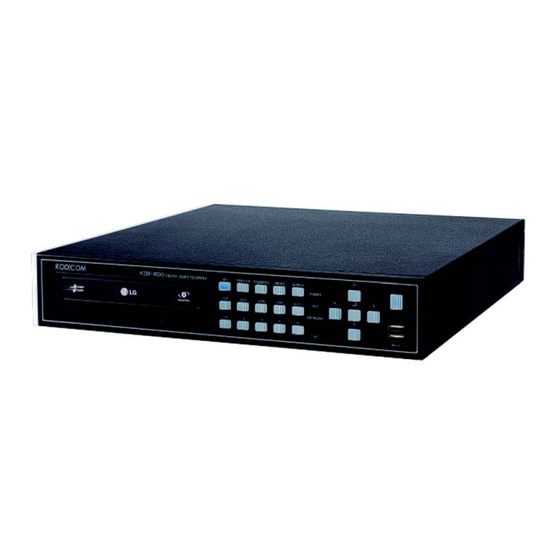
Page 18: Front Panel Description
1.3 Front Panel Description Front panel button and device descriptions. [KDR-400 Front Panel View] Type Feature REC Button • Initiates recording regardless of the schedule • 4 channel split-screen mode. (Available on: all models) DISPLAY Button • 1 channel full-screen mode. - Page 19 Type Feature POWER LED • Indicates the system is powered. REC LED • Indicates the system is recording. NETWORK LED • Indicates network activity. Remote Control • Indicates remote control activity. Indicator Previous • Moves to the previous frame. Frame (4 sec.
-
Page 20: Rear Panel Description
1.4 Rear Panel Description Rear panel input/output descriptions. [KDR-400 Rear Panel View] Type Feature Power Socket • This is the connector for a 12V power socket. Video Input • Input ports for the video signals into the DVR. Through • Output port for each individual video channel from the DVR. -
Page 21: Remote Control
1.5 Remote Control Remote Control button descriptions. Mode Mode 1 : Activate/deactivate Audio Channel 1 Mode 2 : Activate/deactivate Audio Channel 2 PANIC RECORDING Initiates recording for all Select the ID of desired channels. DVR. LIVE/SEARCH Used to switch from the Live PLAYBACK view to the search view and Controls the playback of the... -
Page 22: Installation
2. Installation... -
Page 23: Checking Install Environment
2.1 Checking install environment You should pay attention to the following before you use the product. • Do not use it outdoor. • Do not place water or liquid near the connection part or the product. • Do not impose excessive shock or force. •... - Page 24 Please keep the following instructions for rack-mounting the DVRs to proceed with the installation. 1. The rack on which the DVR is mounted should not be sealed off. 2. And it also can allow air circulation through the vent. 3. As shown in the Figure 2, we recommend you to heap the product with other DVR s or use rack-mount devices at certain space, or install a vent system to accommodate airflow.
-
Page 25: Connecting Video, Audio, And Monitor
2.2 Connecting video, audio , and monitor VIDEO OUT Audio out Video in Video through out SPOT Audio input [Caution] • Since it may have a risk of an electric shock on the video cable connected to the camera according to the grounding state of the power cable, please connect the video cable when the system power is turned off. -
Page 26: Connecting The Network
2.3 Connecting the network 2.3.1 Connecting to Internet through Ethernet (10/100 BaseT) RJ45 Ethernet Cable (Direct Cable) INTERNET Back Bone Hub/Switcher Hub/Switcher Remote Viewer 2.3.2 Connecting to Internet through ADSL RJ45 Ethernet Cable (Direct Cable) INTERNET Phone(ADSL) Line ADSL MODEM Hub/Switcher Remote Viewer... -
Page 27: Connecting The Alarm Input
2.4 Connecting the Alarm Input Connecting one wire of the signal cable (2 wires) of various sensors (such as IR sensor, hot-wire detector and magnetic sensor) to the GROUND port and connect the remaining signal wire to the desired ALARM input port nnumber. [Caution] •... -
Page 28: Connecting The Alarm Output
2.5 Connecting the Alarm Output (-) (+) Such as siren-lamp, amplified External Power siren and external relay Connect one wire of the signal cable (2 wires) of an external device (such as siren- lamp, amplified siren and external replay) to the GROUND port and connect the remaining signal wire to the desired ALARM output port number. -
Page 29: Connecting The Rs485 Device
(+ and -). 2.7 Connecting the USB 1. It has a total of 3 USB connection ports on the front and rear sides of KDR-400. 2. Connect the USB HDD, USB memory through the front/rear ports of KDR-400. -
Page 30: Live Screen
3. Live Screen... -
Page 31: System Behavior
3. Live Screen 3. Live Screen 3.1 System Behavior • When the unit is powered the booting screen in Fig 3-1 should appear. [Booting screen] • System initialization will commence shortly after the booting screen appears. • The live-screen will appear directly following the system initialization. •... -
Page 32: Live-Screen Icons
3.2 Live-Screen Icons Live-screen icon descriptions. Emergency Recording Recording Mode Channel ID Emergency Recording: Appears when the “REC” button on the front panel is pressed. Channel ID: Displays the channel # and given name. Recording Mode: Displays the recording type per camera. Recording Mode Color No Recording... -
Page 33: Dvr Osd & Mode Menu
3.4 DVR OSD & Mode Menus • DVR OSD & mode menu descriptions. These menus can be accessed by the front panel or mouse. Live-Screen OSD (Blue) Sequence Date/Time Mute No Image : Audio OFF & Rec. OFF : Audio ON & Rec. OFF : Audio ON &... -
Page 34: Mouse Pop-Up Menu
3.5 Mouse Pop-up Menu • Mouse pop-up menu descriptions. This menu can be access by right-clicking the mouse. Live-Screen Mode Changes the display mode. (16 ch. split-screen → 9 ch. split-screen → 4 ch. split-screen → 1 ch. full-screen) Switches to the next group of channels within the various display modes. -
Page 35: Setup
4. Setup... -
Page 36: Initial Setup
4. Setup 4. Setup 4.1 Initial Setup • Menu Navigation: The cursor indicates the selected window. Use the arrow keys (▲, ▼, ◀, ▶) to navigated to the desired option. Press [Enter] to execute that option. • Confirmation Buttons: After making the desired changes select [OK] to accept the changes or [CANCEL] to reject the changes. -
Page 37: Login
4.2 Login • Allows multiple user levels to log into the unit. • User levels and passwords can be set for three guest accounts. There are three types of permissions available for these users: search. Backup, network. Only the administrator has access to the setup menu. -
Page 38: Recording Schedule
4.3.1 Recording Schedule • Global Sets the recording schedule and settings for all cameras. • Each Click the button to create a recording schedule for a specific channel. USE : Enable the specified recording schedule. NO. : The recording schedule number. This number cannot be changed. : Select the camera(s) the recording schedule is applied to. -
Page 39: Camera
4.3.2 Camera Registration • Name Enter the desired name of the selected camera. (Max. 15 characters) • Video Loss Enable/disable the video loss beep. • Privacy Enable/disable the privacy mode for the selected channel. The privacy mode hides the selected channel within the live-view mode. -
Page 40: Audio
4.3.3 Audio • Live (Speaker) Enables live audio when in the live-screen mode. • Recording Enables audio recording. [Note] ☞ ☞ • Audio only works for cameras 1 & 2. 4.3.4 HDD • Disk Space Shows the total space and the amount used. •... -
Page 41: Pre-Post Recording
• Take caution when working with the DVR. An electro-static shock may damage the unit. • Kodicom will not be held liable for damage to the HDD due to improper use of the DVR. • Sudden power outages (ie: blackout) may cause damage to the HDD. -
Page 42: Language
4.3.6 Language • The available languages will be listed. Select the desired language and click [OK]. [Note] ☞ ☞ • The system will have to be reset upon changing the language. 4.4 Internet & Network • Internet & Network menu descriptions. -
Page 43: Network Connection
4.4.1 Network Connection • Network Type Select how the DVR is connected to the network. Static IP : The DVR has a static IP. Information of the network must be inputted. DHCP : The DVR is assigned an IP by the server. No input is required. •... -
Page 44: Update Server
• Web Service Port Enter the port number you wish to use for the Remote Viewer S/W. (Available Ports: 1~65534) • Use DDNS A DDNS server is used to map a domain name to an IP address. Check “Use DDNS” to enable the DDNS function. -
Page 45: Display
4.5 Display • Display menu descriptions 4.5.1 Adjustment • The brightness, color, and contrast for each camera can be adjusted. Select the desired channel and press “Enter”. The corresponding video image will open and the adjustments can be made. -
Page 46: Osd
[Note] ☞ ☞ • The brightness, color, and contrast of a channel cannot be modified if the frame rate for that channel is set to 0. 4.5.2 OSD • Ch Info Displays the channel information (number/ID). • Date/Time Displays the date & time. •... -
Page 47: Sequence
4.5.3 Sequence • Setup the sequence order and types of the channels displayed within the live screen. • Duration Select the duration for each screen. (0 Sec(pass), 1~15 Sec, 30 Sec, 60 Sec) • Use the Sequence Mode at Startup Enables the sequence mode directly following the unit initialization. -
Page 48: System
• Channel Select the channel(s) to be displayed on the screen. • Duration Select the duration of the screen (1~15 Sec, 30 Sec, 60 Sec). • DEL. Delete the selected custom spot screen. • Display Camera Name On Screen Enable the camera name to appear on the screen. 4.6 System •... -
Page 49: Date/ Time
• Network Press [Update] to upgrade the firmware via the network. • USB Press [Update] to upgrade the firmware via a USB storage device. • Firmware Displays the current firmware version. [Caution] Firmware upgrade • Do not remove the USB storage devices during installation. Removal of the USB device can cause permanent damage to the system. -
Page 50: System Log
•Time Zone Select the appropriate time zone. • Synchronize NTP Time Click [Update] to use the NTP server to sync the time. (Must have internet connection) [Caution] When the time is set earlier all data in between will be lost. ie: original time 8am →... -
Page 51: Password Parameter
[Caution] Improper shutdown of the system can result in physical damage to the system. Please, shutdown the unit properly. 4.7 Password Parameter • Password Parameter menu description. 4.7.1 Password • Current Password Enter the current admin password. (Default: <none>) • New Password Enter the new password. -
Page 52: Parameter
• GUEST Password Settings GUEST Setup the password for the guest accounts. GUEST1 : Search, Backup, & Network access. GUEST2 : Search & Network access. GUEST3 : Network access only. [Note] ☞ ☞ • Hold (Reset) for 3 seconds to initialize the DVR to the factory password settings. •... -
Page 53: Technical Setting
4.8 Technical Setting • Technical setting menu descriptions. 4.8.1 PTZ & RS-485 Setup the PTZ protocol for the desired camaera. • PTZ ID Choose a PTZ ID. (0~255) • Protocol Select the desired PTZ Protocol (Types: Vicon, Sony, Samsung, Philips, AD, Pelco-P, Pelco-D) •... -
Page 54: Event
[Note] ☞ ☞ • The PTZ settings are dependant on the camera protocol. For more information see the PTZ camera manufacturer’s manual. 4.8.2 Event Notifies the event server in the case of an emergency situation or event. Also sends an event notification to the specified email address. -
Page 55: Alarm Input
4.8.3 Alarm Input • Ch. Select the channel to be recorded when the corresponding alarm is triggered. • Quality Select the quality of the recording. (Best→Better→Good→Normal) • Main Ch. Select the channel to be shown on full-screen when the alarm is triggered. •... -
Page 56: Motion Alarm
4.8.4 Motion Alarm • Motion Alarm Enable/Disable the motion alarm. • Main Ch. Select the channel to be shown on full-screen when motion is detected. • Spot Ch. Select the channel to be shown in the spot channel when motion is detected. •... -
Page 57: Remote Controller
4.8.5 Remote Controller • Button Beep Enable to hear the DVR beep every time a button is pressed on the remote controller. • ID Control Enable to activate the “ID Control” function, to control several DVRs with one remote controller. •... -
Page 58: Etc
4.8.6 ETC. • Alarm Input Select one of two alarm input types: NO (Normal Open) : Alarm is triggered when the switch is closed. NC (Normal Close ) : Alarm is triggered when the switch is open. • Alarm Output Select one of two alarm output types: NO (Normal Open) : Alarm is triggered when the switch is closed. -
Page 59: Search & Playback
5. Search & Playback... -
Page 60: Login
5.1 Login • Log in screen description. • Each guest account has restrictions with access. ☞ [Note] ☞ • If the administrator password is not set the “Log In” screen will be bypassed. 5.2 Search (General Search) • Press [Search] to view recorded data 5 minutes ago. Press to playback the recorded data. -
Page 61: Statistics (Advanced Search)
[Note] ☞ ☞ • Channels with no recorded data will be displayed like the image below. 5.3 Statistics (Advanced Search) • Search through recorded data by: cumulative statistics (time, week, month). Graphical representations will be proportional to the total data. •... -
Page 62: Smart Search (Advanced Search)
5.4 Smart Search (Advanced Search) • Search through recorded data by motion within a specific area of interest. • Calendar Select the desired search date. • Camera ( Select the desired camera to setup/search. • Time Select the desired time of playback. •... -
Page 63: Event Search (Advanced Search)
5.5 Event Search (Advanced Search) • Search through recorded data by specific events, alarms, video loss, type of recording, etc. • Calendar Select the desired search date. • Camera ( Shows the events listed for the desired camera. • Go to Time Jump to the events that occurred after the selected time. -
Page 64: Ptz Control Devices
6. PTZ Control Devices... -
Page 65: Ptz Control Mode
6.1 PTZ Control Mode • The PTZ settings must be set precisely for the PTZ device to operate correctly. (Please refer to section “4.8.1 PTZ & RS-485”.) • The PTZ control mode can only be accessed through the full-screen mode of the desired channel. -
Page 66: Ptz Set Mode
6.2 PTZ Set Mode • The PTZ set mode is used to configure the PTZ control functions. Press within the PTZ Mode to access the Set Mode. • MOVE PRESET Moves the PTZ device to the selected preset position. • CLEAR PRESET Clears the position of the selected preset. -
Page 67: Appendix
Appendix... -
Page 68: Remote Viewer
Remote Viewer Remote Viewer INSTALLATION Type the DVR’s IP address or domain name into the address bar in Microsoft® Internet Explorer™ and press ENTER. When the Security warning window appears, confirm to install the “DVR Remote Viewer”. You should install the remote viewer component manually. Please install DVR Remote Viewer Setup.exe. - Page 69 CONNECTION To connect to your DVR, click the connection button. Select user ID and enter user password, and port in the login dialog box. If you want to save information of Log-In, check “save”. If Log-in succeed, live mode window will be appeared. (Program supports 1024 × 768 resolution) Click <Connected>...
- Page 70 The button descriptions related with the remote viewer’s operation are as follows: FUNCTIONS CONNECT / DISCONNECT MODE SETUP CAPTURE IMAGE MUTE AUDIO SEQUENCE DISPLAY MODE NEXT GROUP SCREEN MODE (FULL/NORMAL) SETUP Set buffering time for stable video Set Duration time transmission via (0, 1, 2, 4, 8, 15, network.
-
Page 71: Audio Setup
STATUS Date/Time DVR Name Transmit Number of frames per connecter second Transmission network band width AUDIO SETUP You can set audio output (1 channel or 2 channel or 1 & 2 channels Mix). <Mute> <1 Channel> <2 Channel> <1&2 Channel> PTZ CONTROL Please change display mode to 1 channel screen mode (want to control channel). - Page 72 PLAYBACK To change PLAYBACK mode, click GO SEARCH To return monitoring mode, click GO LIVE. <STATISTICS MODE> <SMART SEARCH MODE> <EVENT SEARCH MODE> Search process is same as DVR. For more detail see “How to search recorded video”. [Note] ☞ ☞...
- Page 73 If backup window appears on the screen, you can select date and time, channels, and folder to back up. When you click OK button, backup files will be created on this folder(C:₩XDVR). To select other backup folder, press FIND button. If you want to play it, please double-click on file (File name: year month day_time).
-
Page 74: Specification
Specification Specification VIDEO Compression H.264 Level (Professional MPEG-4 DMX-V3) Data Size 0.2KB/frame Image Size D1 Level (704 X 480), CIF Level (352 X 240) Video Input/Output 4CH DVR: 4/4ch TV Output 2 CH (1.0Vpp, 75Ω, BNC) 1 CH (1024 X 768) ※Can be used TV out simultaneously VGA Output Screen Split Control 1,4, Auto sequence... -
Page 75: Faq
3. FAQ 3. FAQ The system power does not turn on. ☞ Check if the power cable is connected correctly. ☞ Check if the input voltage is correct. ☞ If the system power does not turn on when the power cable is connected correctly, please contact the service Center. - Page 76 400 DVR system. It can cause the noise problem to decrease video quality. ☞ Check if the video cable connecting the camera to KDR-400 DVR system is the correct video cable. When a normal power-supplying cable is used instead of the video cable, screen noise can be generated.
-
Page 77: Warranty Guide
4. Damaged due to incorrect power voltage, and/or frequency being used. 5. If the Product Warranty has expired. 6. Damaged due to anyone not employed by Kodicom modifying the system. If your system is damaged after the expiration of the warranty period, free repair service will not be available. If you wish the system to be repaired, a service fee and replacement parts will be charged on a time &...
Need help?
Do you have a question about the KDR-400 and is the answer not in the manual?
Questions and answers