Table of Contents
Advertisement
Advertisement
Table of Contents

Subscribe to Our Youtube Channel
Related Manuals for Samson C-com opti


Summary of Contents for Samson C-com opti
- Page 1 -2 -1 SAMSON OPTICAL COMPRESSOR...
-
Page 2: Safety Instructions
Safety Instructions Caution: To reduce the hazard of electrical shock, do not remove cover or back. No user serviceable parts inside. Please refer all servicing to qualified personnel. WARNING: To reduce the risk of fire or electric shock, do not expose this unit to rain or moisture. The lightning flash with an arrowhead symbol within an equilateral triangle, is intended to alert the user to the presence of uninsulated "dangerous voltage"... -
Page 3: Table Of Contents
C com opti Connections Stacking and Installing the Tilting Feet Installing the Optional CRK1 Dual Rack adapter Specifications C com opti Block Diagram Copyright 2003, Samson Technologies Corp. Printed June, 2003 Samson Technologies Corp. 575 Underhill Blvd. P.O. Box 9031... -
Page 4: Introduction
Output Level or Gain Reduction. For stereo operation, two C com opti’s can be joined together using the LINK input allowing the two units to operate as one stereo device. Like all Samson Audio C class processors, the C com opti can be stacked on other C class models, and can be set-up on an angle using the included tilting feet. -
Page 5: C Com Opti Features
C com opti Features -2 -1 SAMSON The Samson C com opti optical compressor utilizes a unique photo cell design which produces a classic sound while han- dling the job of gain management . Here are some of its main features: •... -
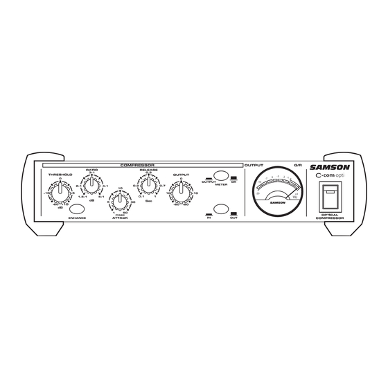
Page 6: Front Panel Layout
C com opti Layout Front Panel Layout -2 -1 SAMSON THRESHOLD - Used to set the minimum signal level MAINS POWER SWITCH - When pressed on, at which the compressor circuit begins to function. the green LED lights indicating that the C com opti is powered up and ready for operation. -
Page 7: Operating The C Com Opti
Next, turn on your mixer and monitor system, but keep the listening level low until you become more familiar with your new processor. • Set the controls to the following default positions: -2 -1 SAMSON COMPRESSOR THRESHOLD +10dBu (fully clockwise) ENHANCER SWITCH OUT (YELLOW LED OFF) RATIO 1.5 : 1 (fully counter-clockwise) -
Page 8: Compressing A Signal
Operating The C com opti COMPRESSING A SIGNAL C com opti’s compressor section can be used for a variety of gain management tasks including printing signals to a multi-track recorder, as a mix-down effect, mastering, and for increasing the loudness of a live PA system. To begin com- pressing your signal, follow the steps below: •... -
Page 9: Using The Enhancer
Operating The C com opti USING THE ENHANCER The C com opti’s ENHANCER switch can be engaged to activate the EFR (Enhanced Frequency Recovery) cir- cuit. By engaging the ENHANCER, the C com opti EFR restores the high frequency content that can be lost when high gain reduction is applied. -
Page 10: System Set-Ups
INSERT POINT COMPRESSION -2 -1 -2 -1 SAMSON SAMSON In this example, two C com opti’s are used individually to compress the signal of the bass and keyboard tracks. The C com opti’s are connected to the mixer’s insert points using a standard 1/4-inch insert “Y” cable. See page 13 for a detailed wiring diagram. -
Page 11: Dynamics Processing 101
Dynamics Processing 101 To begin to understand dynamics processing, we must first understand what dynamics are. Dynamics, or the dynamic range of a signal or audio device, is the amount of level between the softest and loudest possible out- put. Dynamics processing is applied to a signal to manage the changes in level. Various types of processing units are available to control dynamics including Noise Gates, Expanders, Compressors, Limiters and De-Essers. -
Page 12: Applications
Applications Leveling a Vocal Track When recording a vocal track, the vocalist may change the distance between them and the microphone, or they may naturally have a lot of dynamic range in their performance. In either case, the sound engineer must decide how much compression should be used to balance the natural performance and printing a good level to tape or disk. -
Page 13: C Com Opti Connections
C com opti Connections CONNECTING THE C com opti The are several ways to interface the C com opti to support a variety of applications. The C com opti features servo-balanced inputs and outputs, so connecting balanced and unbalanced signals is possible without any sig- nal loss. -
Page 14: Stacking And Installing The Tilting Feet
Stacking and Tilting the C com opti Stacking the C com opti You can stack one C com opti, or any other Samson C Class units, on top of each other by simply lining up the bumpers. Important Note: When... -
Page 15: Installing The Optional Crk1 Dual Rack Adapter
Installing the Optional CRK1 Dual Rack Adapter The C Class Dual Rack Adapter is available as an accessory from an authorized Samson dealer. 1. Disconnect any cables, that may be connected, from the C•Class unit to be mounted, i.e., the power supply cable, audio cables, headphones. -
Page 16: Specifications
Specifications System Specifications Frequency Response 20Hz to 20kHz + - 0.5 dB Dynamic range 95 dBu, un-weighted, 22 Hz to 22 kHz Max Input Level +28 dBu Compressor Section Threshold -20 dB to +10 dB Ratio variable (1:5 to 5.1 ) Attack Time variable (1 to 50 msec) ReleaseTime... -
Page 17: C Com Opti Block Diagram
C com opti Block Diagram... - Page 18 Notes...
- Page 20 Samson Technologies Corp. 575 Underhill Blvd. P.O. Box 9031 Syosset, NY 11791-9031 Phone: 1-800-3-SAMSON (1-800-372-6766) Fax: 516-364-3888 www.samsontech.com...
Need help?
Do you have a question about the C-com opti and is the answer not in the manual?
Questions and answers