Table of Contents
Advertisement
Advertisement
Table of Contents

Subscribe to Our Youtube Channel
Related Manuals for Standard Horizon HX370E


Summary of Contents for Standard Horizon HX370E
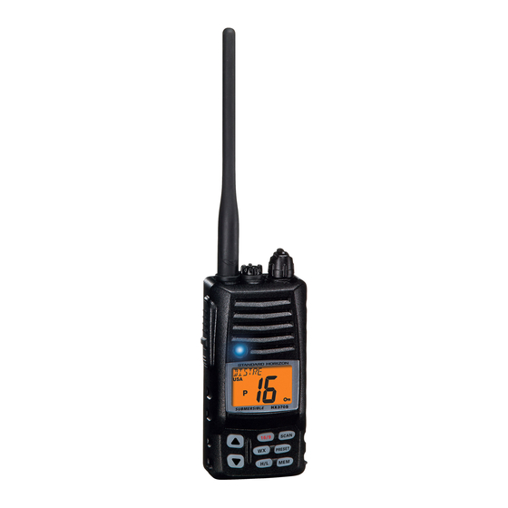
- Page 1 HX370E VHF/FM Marine Handheld Transceiver Owner's Manual HX370E...
-
Page 2: Table Of Contents
If you use a headset accessory for this radio, with the radio worn on your body, use only the STANDARD HORIZON belt clip for this transceiver, and ensure that the antenna is at least 1 inches (2.5 centimeters) from your body when transmitting. - Page 3 Congratulations on your purchase of the HX370E! Whether this is your first portable marine VHF transceiver, or if you have other STANDARD HORIZON equipment, the STANDARD HORIZON organization is committed to ensur- ing your enjoyment of this high-performance transceiver, which should pro- vide you with many years of satisfying communications even in the harshest of environments.
-
Page 4: General Information
1. GENERAL INFORMATION 1.1 INTRODUCTION The HX370E is a submersible, miniature 5-Watt portable two-way VHF ma- rine transceiver. The transceiver has all allocated USA, international, or Canadian channels. It has an emergency channel 16 which can be immedi- ately selected from any channel by pressing the 16/9 key. -
Page 5: Accessories
DC Cable; plug and wire only VAC-370B/C/U Rapid charger 120/230 VAC CE68 PPS Software CT-111 Cable SET for CE68 CAW230 Radio-to-Ship’s-Antenna Adapter Note: Before operating the HX370E for the first time, it is recommended that the bat- tery be charged. HX370E Page 3... -
Page 6: Battery
3. BATTERY The FNB-83 and FNB-V57IS (intrinsically Safe Version) are high perfor- mance rechargeable battery providing high capacity in a compact package. Note: FNB-83 is supplied with the HX370E and the FNB-V57IS is supplied with the “IS Version” only. CAUTION... -
Page 7: Using The Nc
3.3 USING THE NC-88 BATTERY CHARGER 1. Install the supplied FNB-83/FNB-V57IS battery pack on the rear of the HX370E. Ensure that the transceiver is switched off. 2. Plug the NC-88 Overnight Charger into the AC line outlet, then insert the cable plug into the jack located on the side panel of the CD-26 Charger Cradle. -
Page 8: Battery Safety
Never short-circuit the connection terminals on the bat- tery or charger ! CONTAINS NICKEL-METAL-HYDRIDE BATTERY. MUST BE RECYCLED OR DISPOSED OF PROP- ERLY. Ni-MH CONTAINS NICKEL-CADMIUM BATTERY. MUST BE RECYCLED OR DISPOSED OF PROPERLY Page 6 HX370E... -
Page 9: Controls And Indicators
This section defines each control of the transceiver. For detailed oper- ating instructions, refer to section 5 of this manual. Refer to Figure 3 for the location of the following controls, indicators, and connections. Figure 3 Controls and Connectors HX370E Page 7... -
Page 10: Controls And Connections
Accepts the optional CMP460, MH-57 speaker microphone or VC-24 VOX Headset. When this jack is used, the internal speaker is disabled. Do not allow the HX370E to become submerged in water while the plastic cover over the MIC/SP jack is removed. Antenna Connector The supplied CAT460 flexible antenna is attached here. - Page 11 (shown as - on the LCD). Pressing this key repeatedly scrolls through the preset memory channels. MEM KEY Press to select a channel for scanning. Press this key again to delete a memorized channel. (“MEM” appears on the LCD display during memory operation). HX370E Page 9...
-
Page 12: Indicators
” is for Low power (1 Watt). “Blank” in this location indicates a re- ceive-only channel. P Indicator Ch16 Priority Scan is activated. DW Indicator Dual watch is activated. SCN Indicator Scan is activated. TX Indicator Appears during transmission. Page 10 HX370E... - Page 13 NOTE: The battery indicator should be used only as a guide in charging the FNB-83/FNB-V57IS battery. KEY Lock Indicator When the “ ” symbol is shown on the LCD, all keys are disabled except for the H/L, PTT and SQL keys. HX370E Page 11...
-
Page 14: Operation
Figure 5 Antenna Installation Installing the Quick Draw Belt Clip 1. Connect the hanger to the rear of the HX370E, with the notch point- ing directly up, using the supplied screw (Figure 6-a). Use only the screw included with the clip to mount the clip to the back of the transceiver! 2. -
Page 15: Reception
” sym- bol will disappear from the display. LMR (Land Mobile Radio) Channels The HX370E is capable of PC programming 40 LMR (Land Mobile Ra- dio) channels by a dealer. Contact your dealer for further details. Typical display of LMR operation. -
Page 16: Transmission
8. When the transmission is finished, release the PTT switch. 5.4 TRANSMIT TIME - OUT TIMER (TOT) The HX370E is capable of PC programming TRANSMIT TIME - OUT TIMER (TOT) by a dealer. Contact your dealer for further details. While the PTT switch is held down, transmission time is limited to 5 minutes. -
Page 17: Usa, Canadian, And International Bands
Scanning will resume when the squelch closes after the incoming signal disappears at the end of the transmission. 8. To stop the scan, press the SCAN, 16/9, or DW key. HX370E Page 15... -
Page 18: Programmable Priority Scan
A small “DW” icon will be shown blinking on the left of the display during scanning. 2. To cancel the Dual Watch feature, press the DW key. Page 16 HX370E... -
Page 19: Emergency (Channel 16 Use)
U.S. waters by using Channel 9 as the initial contact (hailing) channel for non-emergency communications. Here, also, calling time should not exceed 30 seconds but may be repeated 3 times at 2-minute intervals. HX370E Page 17... -
Page 20: Operating On Channel 13
When channel 67 is used for navigational bridge-to-bridge traffic between ships, High or Medium power may be used temporarily (in the USA band) by pressing the H/L key. When the PTT switch released, the transceiver will revert to low power. Page 18 HX370E... -
Page 21: Preset Channels (1 ~ 8)
“1” to the right of the channel number on the LCD for 1 second, and channel 2 is represented by “2,” and so forth. Then the preset channel numberr will disappear and the display comes back to the normal channel display. HX370E Page 19... -
Page 22: Simplex/Duplex Channel Use
5.15 ENABLING S.O.S STROBE OPERATION The S.O.S. STROBE feature utilizes the high-intensity strobe LED on the front of the HX370E as a visual distress beacon. When enabled, the LED blinks the internationally-recognized Morse Code “S.O.S.” message ( • • • – – – • • • ) at a rate of 5 words per minute. This can be very useful in summoning help from rescuers who may not be able to communicate with you via radio. -
Page 23: Voice Scrambler Unit
3. Align the connector on the FVP-31 with the transceiver’s connector and gently press the unit into place. 4. Place the Sponge Sheet (supplied with the HX370E) on the FVP-31. 5. Affix the new (supplied with the FVP-31) caution seal, and replace the battery. -
Page 24: Setup Mode
5.17 SETUP MODE The HX370E’s Setup Mode allows a number of the HX370E operating pa- rameters to be custom-configured for your operating requirements. The Setup Mode is easy to activate and set, using the following procedure: 1. Turn the radio off. - Page 25 5.17.4 dUL ( DW D ISPLAY Function: Selects the Dual Watch scanning display mode. Available Values: Normal/Special Default: Special When “Special” is selected, channel number which is the LCD shows re- ceived channel. HX370E Page 23...
- Page 26 This lets you see the last channel on which someone called. Normal Special 5.17.8 SCr ( V ) [ Requires optional FVP-31 ] OICE CRAMBLER Function: Enable/Disable the Voice Scrambler. Available Values: OFF/SC0/SC1/SC2/SC3 Default: OFF Code “SC0” Code “SC1” Code “SC2” Code “SC3” Page 24 HX370E...
-
Page 27: Cloning
5.18 CLONING The HX370E includes a convenient “Clone” feature, which allows the memory and configuration data from one transceiver to be transferred to another HX370E. 1. Turn both radios off. 2. Connect the (optional) CT-32 Clone Cable between the MIC/SP jacks of the two transceivers. -
Page 28: Maintenance
Keep the microphone connected or the jack covered at all times to pre- vent corrosion of electrical contacts; Never key the transmitter unless an antenna or suitable dummy load is connected to the antenna receptacle. Use only STANDARD HORIZON-approved accessories and replacement parts. TROUBLESHOOTING CHART PROBABLE... -
Page 29: Channel Assignments
And you still must release the push-to-talk switch after each transmission in order to listen to the radio. 5. Channels normally used by recreational boaters are those that include the term “non-commercial” in the Channel Use column of the chart. Some HX370E Page 27... - Page 30 157.050 161.650 Port operation, ship movement 21A X X 157.050 U.S. Government Only, Canadian Coast Guard 157.100 161.700 Port operation, ship movement US and Canadian Coast Guard Liaison and Maritime 22A X X 157.100 Safety Information Broadcasts announced on channel 16 Page 28 HX370E...
- Page 31 Port Operations ( Inter-ship only ) (1W) Port Operations ( Inter-ship only ) (1W) 156.875 Port Operations ( Inter-ship only ) 156.875 Public Correspondence ( Marine Operator ) , 156.925 161.525 Port operation, ship-movement Non-commercial ( Recreational ) 78A X X 156.925 HX370E Page 29...
- Page 32 X X X 157.425 162.025 Public Correspondence ( ship-to-coast ) X X X 88A X 157.425 Commercial, Inter-ship Only The above channels are not for use of the general public in U.S. waters, unless proper authorization is given. Page 30 HX370E...
- Page 33 156.525 156.525 157.350 161.950 Noncommercial 157.375 161.975 157.400 162.000 156.425 156.425 157.425 162.025 156.450 156.450 156.475 156.475 156.575 156.575 156.625 ..Intership only. 156.925 156.925 156.975 156.975 Great Lakes only. 157.025 157.025 Do. 156.375 ..Internship only. HX370E Page 31...
- Page 34 Gulf Outlet Canal from entrance to its junction with the Inner Harbor Navigation Canal, and over the ull length of the Inner Harbor Navigation Canal from its junc- tion with the Mississippi River to its entry to Lake Pontchartrain at the New Seabrook vehicular bridge. Page 32 HX370E...
- Page 35 17. The frequency 156.425 MHz is assigned by rule to private coast stations in Alaska for facsimile transmissions as well as voice communications. HX370E Page 33...
-
Page 36: Specifications
Spurious and Image Rejection: 70 dB Hum and Noise: 40 dB Selectivity: 12 kHz / 25 kHz (–6 dB/–60 dB) (Wide) 6 kHz / 18 kHz (–6 dB/–60 dB) (Narrow) AF output: 600 mW @ 16 Ohm for 10 % THD (@7.2V) Page 34 HX370E... - Page 37 MEMO HX370E Page 35...
- Page 38 MEMO Page 36 HX370E...
- Page 39 HX370E...
- Page 40 VERTEX STANDARD CO., LTD. 4-8-8 Nakameguro, Meguro-Ku, Tokyo 153-8644, Japan VERTEX STANDARD US Headquarters 10900 Walker Street, Cypress, CA 90630, U.S.A. YAESU EUROPE B.V. Copyright 2004 P.O. Box 75525, 1118 ZN Schiphol, The Netherlands YAESU UK LTD. VERTEX STANDARD CO., LTD. Unit 12, Sun Valley Business Park, Winnall Close All rights reserved.
Need help?
Do you have a question about the HX370E and is the answer not in the manual?
Questions and answers