
Related Manuals for Rabbit Wildcat BL2000


Summary of Contents for Rabbit Wildcat BL2000
- Page 1 Wildcat (BL2000) C-Programmable Single-Board Computer with Ethernet User’s Manual 019–0094 • 090529–O...
- Page 2 Rabbit and Dynamic C are registered trademarks of Digi International Inc. Rabbit 2000 is a trademark of Digi International Inc. The latest revision of this manual is available on the Rabbit Web site, www.rabbit.com, for free, unregistered download. Digi International Inc.
-
Page 3: Table Of Contents
ABLE OF ONTENTS Chapter 1. Introduction 1.1 BL2000 Description..........................1 1.2 BL2000 Features...........................1 1.2.1 Connector Options ........................2 1.3 Development and Evaluation Tools......................3 1.3.1 Tool Kit ............................3 1.3.2 Software ............................4 1.4 CE Compliance .............................5 1.4.1 Design Guidelines .........................6 1.4.2 Interfacing the BL2000 to Other Devices ..................6 Chapter 2. - Page 4 A.1 Electrical and Mechanical Specifications..................60 A.1.1 Headers ............................63 A.2 Conformal Coating ..........................64 A.3 Jumper Configurations ........................65 A.4 Use of Rabbit 2000 Parallel Ports ..................... 67 Appendix B. Plastic Enclosure B.1 Assembly ............................70 B.2 Dimensions ............................72 Appendix C.
-
Page 5: Chapter 1. Introduction
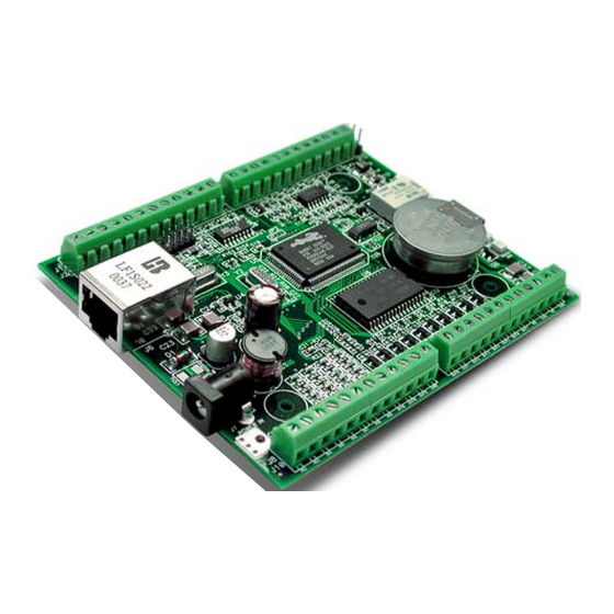
1.1 BL2000 Description The BL2000 is an advanced single-board computer that incorporates the powerful Rabbit 2000 microprocessor, flash memory, static RAM, digital I/O ports, A/D converter inputs, D/A converter outputs, an SPDT relay output, and a 10Base-T Ethernet port. -
Page 6: Connector Options
In addition to the standard screw-terminal connectors supplied on BL2000 boards, IDC headers, bottom-mount connectors, and polarized friction-lock terminals may be factory- installed instead. Visit our Web site at www.rabbit.com or contact your Rabbit sales repre- sentative or authorized distributor for further information. “Bottom-mount connector” to Standard screw terminals, accept mount BL2000 directly on 0.1"... -
Page 7: Development And Evaluation Tools
PC’s CD-ROM drive. If the installation does not auto-start, run the setup.exe program in the root directory of the Dynamic C CD. Install any Dynamic C modules after you install Dynamic C . Rabbit and Dynamic C are registered trademarks of Digi International Inc. Getting Started... -
Page 8: Software
1.3.2 Software The BL2000 is programmed using version 7.04 or later of Rabbit’s Dynamic C. A compat- Dynamic C v. 9.60 includes the popular ible version is included on the Tool Kit CD-ROM. µC/OS-II real-time operating system, point-to-point protocol (PPP), FAT file system, RabbitWeb, and other select libraries that were previously sold as individual Dynamic C modules. -
Page 9: Ce Compliance
These limits apply over the range of 30–230 MHz. The limits are 7 dB higher for frequen- cies above 230 MHz. Although the test range goes to 1 GHz, the emissions from Rabbit- based systems at frequencies above 300 MHz are generally well below background noise levels. -
Page 10: Design Guidelines
• When connecting the BL2000 single-board computer to outdoor cables, the customer is responsible for providing CE-approved surge/lighting protection. • Rabbit recommends placing digital I/O or analog cables that are 3 m or longer in a metal conduit to assist in maintaining CE compliance and to conform to good cable design practices. -
Page 11: Chapter 2. Getting Started
2. G ETTING TARTED Chapter 2 explains how to connect the programming cable and power supply to the BL2000. 2.1 BL2000 Connections 1. Attach the BL2000 to the plastic enclosure base. Position the BL2000 over the plastic enclosure base as shown below in Figure 2. Attach the BL2000 to the base at the top left and bottom right positions using the two 4-40 ×... - Page 12 2. Connect the programming cable to download programs from your PC and to debug the BL2000. Connect the 10-pin PROG connector of the programming cable to header J5 on the BL2000. Ensure that the colored edge lines up with pin 1 as shown. (Do not use the connector, DIAG .) Connect the other end of the programming...
- Page 13 3. Connect the power supply. First, prepare the AC adapter for the country where it will be used by selecting the plug. The BL2000 Tool Kit presently includes Canada/Japan/U.S., Australia/N.Z., U.K., and European style plugs. Snap in the top of the plug assembly into the slot at the top of the AC adapter as shown in Figure 4, then press down on the spring-loaded clip below the plug assembly to allow the plug assembly to click into place.
-
Page 14: Installing Dynamic C
2.2 Installing Dynamic C If you have not yet installed Dynamic C version 7.04 (or a later version), do so now by inserting the Dynamic C CD in your PC’s CD-ROM drive. The CD will auto-install unless you have disabled auto-install on your PC. If the CD does not auto-install, click Start >... -
Page 15: Starting Dynamic C
If you receive the message , the programming No Rabbit Processor Detected cable may be connected to the wrong COM port, a connection may be faulty, or the target system may not be powered up. First, check both ends of the programming cable to ensure that it is firmly plugged into the PC and the programming port. -
Page 16: Pong.c
Section 5.3, “Run the PINGME.C Sample Program,” tests the TCP/IP portion of the board. 2.5 Where Do I Go From Here? NOTE: If you purchased your BL2000 through a distributor or Rabbit partner, contact the distributor or partner first for technical support. If there are any problems at this point: •... -
Page 17: Chapter 3. Subsystems
Chapter 3 describes the principal subsystems for the BL2000. • Digital I/O • Relay Outputs • Serial Communication • A/D Converter Inputs • D/A Converter Outputs • Memory • External Interrupts Figure 5 shows these Rabbit-based subsystems designed into the BL2000. Digital BL2000 Inputs Programming Port Digital RS-232... -
Page 18: Bl2000 Pinouts
3.1 BL2000 Pinouts The BL2000 pinouts are shown in Figure 6(a) and Figure 6(b). +RAW /RESET 485– Serial Port Nomenclature 485+ HeaderJ2 Rabbit 2000 IN10 RXD2 TXD1 OUT8 TXD2 RXD1 OUT9 RXD1 TXD2 TxC/RTS RXD2 RxC/CTS TXD1 AGND OUT0 DAC1... -
Page 19: Headers And Screw Terminals
• 1 × 17 bottom-mount sockets with a pitch of 0.1". The holes for the bottom-mount sockets are on the “outside” edges of the connector locations The pinouts for these connectors are shown in Figure 6(b). +RAW /RESET 485– Serial Port Nomenclature 485+ Rabbit 2000 HeaderJ2 IN10 RXD2 TXD1 OUT8 TXD2 RXD1... -
Page 20: Power Supply Pins
3.1.2 Power Supply Pins Instead of connecting an AC adapter to the power supply jack, J7, the input power supply (9 V to 40 V DC) may be connected to pins 12 and 11 on header J2 (see Figure 6(a) or Figure 6(b)). -
Page 21: Digital I/O
JP6 as shown in Figure 7. Factory Default 27 kW 22 kW Rabbit 2000 ™ 10 nF Microprocessor Figure 7(a). BL2000 Digital Inputs [Pulled Up—JP6(1–2) connected] 27 kW +5 V 22 kW Rabbit 2000 ™... - Page 22 27 kW 22 kW Rabbit 2000 ™ 10 nF Microprocessor Figure 7(c). Example of Logic Gate Driving BL2000 Digital Input The actual switching threshold is approximately 2.40 V for channels IN0–IN10. Anything below this value is a logic 0, and anything above is a logic 1...
-
Page 23: Digital Outputs
3.2.2 Digital Outputs The BL2000 has 10 digital outputs, OUT0–OUT9, each of which can either sink or source up to 200 mA, depending on how the outputs are configured. On boards that carry the CE mark, OUT8 and OUT9 are each capable of sinking up to 750 mA. Each output can be configured individually as either a sinking or a sourcing output as shown in Figure 9. - Page 24 Figure 9. BL2000 Digital Outputs The locations of the output pull-up/pull-down select resistors R32, R34, and R35 are shown in Figure 10. SRAM R41 R42 R46 R47 R48 R49 R43 R44 R45 D10 D11 D12 POWER IN GN D GN D IN10 OUT8 OUT9 GND OUT0 OUT1 OUT2 OUT3 OUT4 OUT5 OUT6 OUT7 GND/VCC...
-
Page 25: Relay Outputs
Microprocessor Figure 11. BL2000 Relay Output Contact Connections The relay is driven by PA0, which is the same Rabbit 2000 parallel port that drives OUT0 and LED DS4. OUT0 therefore works in parallel with the relay output. The relay included on the BL2000 has contacts rated for 1 A @ 30 V DC or 300 mA @ 120 V AC. -
Page 26: Serial Communication
RS-232 can be used effectively at this baud rate for distances up to 15 m. 3.4.2 RS-485 The BL2000 has one RS-485 serial channel, which is connected to the Rabbit 2000 Serial Port D through U8, an RS-485 transceiver. U8 supports the RS-485 serial communication protocol. - Page 27 Ground recommended /RESET 485– 485+ Figure 12. Multidrop BL2000 Network User’s Manual...
-
Page 28: Ethernet Port
The BL2000 comes with a 220 Ω termination resistor and two 681 Ω bias resistors installed and enabled with jumpers across pins 1–2 and 3–4 on header JP1, as shown in Figure 13. Factory 485+ Default bias 681 W termi- RXD1 TXD1 AGND DAC1 DAC0 ADC8 ADC7 ADC6 ADC5 ADC4 ADC3 ADC2 ADC1 ADC0 220 W... -
Page 29: Programming Port
3.4.4 Programming Port The BL2000 has a 10-pin programming header labeled J5. The programming port uses the Rabbit 2000’s Serial Port A for communication. Dynamic C uses the programming port to download and debug programs. The programming port is also used for the following operations. - Page 30 2. It can be driven low during an interrupt acknowledge cycle. 3. It can also serve as a general-purpose output. The /RESET_IN pin is an external input that is used to reset the Rabbit 2000 and the onboard peripheral circuits on the RabbitCore module. The serial programming port can be used to force a hard reset on the RabbitCore module by asserting the /RESET_IN signal.
-
Page 31: A/D Converter Inputs
3.5 A/D Converter Inputs The single 14-channel A/D converter used in the BL2000 has a resolution of 12 bits (models BL2000 and BL2020) or 10 bits (models BL2010 and BL2030). Eleven of the 14 channels are available externally, and three are used internally for the reference voltages: 4.096 V ), 2.048 V (V /2), and Analog Ground. -
Page 32: D/A Converter Outputs
3.6 D/A Converter Outputs Figure 18 shows the analog voltage reference circuit. 100 W DAC_PWR 4.096_VREF 100 nF 453 W 14 kW 1.707_VREF 10 kW 100 nF Figure 18. Analog Reference Voltages This circuit generates the 4.096 V reference voltage, which is used by the A/D converter and optionally by the two D/A converters. - Page 33 Only the BL2000 and the BL2020 models are stuffed with D/A converters. The D/A con- verters provide only a voltage output. This means that in order to maintain the maximum accuracy of the D/A converters, only a small amount of current should be drawn from the D/A converter output (of the order of µA).
-
Page 34: Memory
SRAM size. The “jumpers” are 0 Ω surface-mounted resistors. NOTE: Rabbit recommends that any customer applications should not be constrained by the sector size of the flash memory since it may be necessary to change the sector size in the future. -
Page 35: Programming Cable
When the Rabbit 2000 is reset, the operating mode is determined by the status of the SMODE pins. When the programming cable’s PROG connector is attached, the SMODE pins are pulled high, placing the Rabbit 2000 in the Program Mode. When the programming cable’s connector is not attached, the PROG SMODE pins are pulled low, causing the Rabbit 2000 to operate in the Run Mode. -
Page 36: Other Hardware
3.9 Other Hardware 3.9.1 External Interrupts BL2000 boards with a Rabbit 2000 microprocessor labeled IQ3T or higher have external interrupts available on digital inputs IN2 and IN3. Older BL2000 boards (Rabbit 2000 microprocessors labeled IQ2T) have one external interrupt available—see Technical Note TN301, Rabbit 2000 Microprocessor Interrupt Problem, for further information on how to use this interrupt on the older boards. -
Page 37: Spectrum Spreader
3.9.3 Spectrum Spreader BL2000 boards that carry the CE mark have a Rabbit 2000 microprocessor that features a spectrum spreader, which helps to mitigate EMI problems. By default, the spectrum spreader is on automatically for BL2000 boards that carry the CE mark when used with Dynamic C 7.32 or later versions, but the spectrum spreader may also be turned off or set... - Page 38 Wildcat (BL2000)
-
Page 39: Chapter 4. Software
Dynamic C is an integrated development system for writing embedded software. It runs on an IBM-compatible PC and is designed for use with Rabbit-based single-board computers and other devices based on the Rabbit microprocessor. Chapter 4 provides the libraries, function calls, and sample pro- grams related to the BL2000. - Page 40 LCD display and keypad drivers. • Powerful language extensions for cooperative or preemptive multitasking • Loader utility program to load binary images into Rabbit-based targets in the absence of Dynamic C. • Provision for customers to create their own source code libraries and augment on-line help by creating “function description”...
-
Page 41: Upgrading Dynamic C
The default installation of a patch or bug fix is to install the file in a directory (folder) dif- ferent from that of the original Dynamic C installation. Rabbit recommends using a differ- ent directory so that you can verify the operation of the patch without overwriting the existing Dynamic C installation. -
Page 42: Sample Programs
4.2 Sample Programs Sample programs are provided in the Dynamic C folder. The sample program SAMPLES demonstrates the output to the window. The various directories in the STDIO PONG.C folder contain specific sample programs that illustrate the use of the correspond- SAMPLES ing Dynamic C libraries. -
Page 43: Serial Communication
—Demonstrates the use of Timer B to generate a PWM signal on digital output • PWM.C OUT8. The program generates a 42 Hz PWM signal with the duty cycle adjustable from 1 to 99%. —Demonstrates how to control the relay on the BL2000. •... -
Page 44: D/A Converter Outputs
4.2.5 D/A Converter Outputs The following sample programs are found in the subdirectory in SAMPLES/BL2000 —This program demonstrates how to recalibrate an D/A converter channel • DACAL.C using two known voltages, and defines the two coefficients, gain and offset, that will be rewritten into the D/A converter's EEPROM simulated in flash memory. -
Page 45: Bl2000 Libraries
—libraries associated with features specific to the BL2000. • BL2000- —libraries specific to using TCP/IP functions on the BL2000. • TCPIP Other generic functions applicable to all devices based on the Rabbit 2000 microprocessor are described in the Dynamic C Function Reference Manual. User’s Manual... -
Page 46: Bl2000 Function Calls
4.4 BL2000 Function Calls 4.4.1 Board Initialization void brdInit (void); Call this function at the beginning of your program. This function initializes the system I/O ports and loads all the A/D and DAC calibration constants from flash memory into SRAM for use by your pro- gram. - Page 47 Output Function Port Function State Output RTS/TXC RS-232 Inactive high Input CTS/RXC RS-232 Output TXB RS-232 Inactive high Input RXB RS-232 Output TXA Programming Port Inactive high Input RXA Programming Port Output DAC-ADC_SK Output DAC-ADC_SDI Input RTL-ADC_SDO Input RTL_SK Output RTL_SDI Output DAC0_CS...
-
Page 48: Digital I/O
OUTPUT_DRIVE SOURCING The relay is driven by PA0, which is the same Rabbit 2000 parallel port that drives OUT0 and LED DS4. OUT0 therefore works in parallel with the relay output. Rabbit therefore recommends that you do not use OUT0 for a digital output when you are using the relay. -
Page 49: Serial Communication
For more information, see the Dynamic C Function Reference Manual and Technical Note 213, Rabbit Serial Port Software. The following function calls are specific to the BL2000. -
Page 50: Relay And Led Outputs
Sets the state of a relay. The relay is driven by PA0, which is the same Rabbit 2000 parallel port that drives OUT0 and LED DS4. OUT0 therefore works in parallel with the relay output. Rabbit therefore recommends that you do not use OUT0 for a digital output when you are using the relay. -
Page 51: A/D Converter Inputs
4.4.5 A/D Converter Inputs void anaInCalib(int channel, int value1, float volts1, int value2, float volts2); Calibrates the response of the A/D converter channel as a linear function using the two conversion points provided. Gain and offset constants are calculated and placed into global table _adcInCalib PARAMETERS channel... - Page 52 TLC1543 commands (the TLC1543 is a 10-bit A/D converter) D7–D4 Channel 0 - 10 Channel 11 = (Vref+ - Vref-)/2 Channel 12 = Vref- Channel 13 = Vref+ (No software power-down mode available) D3–D0 No specific values assigned. PARAMETERS is the A/D converter input channel (0–10) to read. is the output data length: 0 = 12-bit mode (BL2000/BL2020 only) 1 = 8-bit mode (BL2000/BL2020 only)
- Page 53 float anaInVolts(unsigned int channel); Reads the state of an A/D converter input channel and uses the previously set calibration constants to convert it to volts. PARAMETER channel is the A/D converter input channel (0–10). RETURN VALUE A voltage value corresponding to the voltage on the analog input channel. SEE ALSO anaIn, anaInCalib, brdInit int anaInEERd(unsigned int channel);...
-
Page 54: D/A Converter Outputs
4.4.6 D/A Converter Outputs The functions in this section apply only to the BL2000 and the BL2020 models. int anaOutCalib(int channel, int value1, float volts1, int value2, float volts2); Calibrates the response of the D/A converter channel desired as a linear function using the two conver- sion points provided. - Page 55 void anaOut(unsigned int channel, unsigned int modecount); Sets the voltage of a D/A converter output channel by serially clocking in 16 bits to a D/A converter using the following format: D15–D14 Doesn’t matter. D13–D12 Mode of operation 00—Normal Operation 01—Software Powerdown, 1 kΩ to GND 10—Software Powerdown, 100 kΩ...
- Page 56 void anaOutVolts(unsigned int channel, float voltage); Sets the voltage of a D/A converter output channel by using the previously set calibration constants to calculate the correct data values. PARAMETERS channel is the D/A converter output channel (0 or 1). voltage is the voltage desired on the output channel.
-
Page 57: Chapter 5. Using The Tcp/Ip Features
• Two RJ-45 straight through Ethernet cables and a hub, or an RJ-45 crossover Ethernet cable. The Ethernet cables and Ethernet hub are available from Rabbit in a TCP/IP tool kit. More information is available at www.rabbit.com. 1. Connect the AC adapter and the programming cable as shown in Chapter 2, “Getting Started.”... - Page 58 The PC running Dynamic C through the serial programming port on the BL2000 does not need to be the PC with the Ethernet card. 3. Apply Power Plug in the AC adapter. The BL2000 is now ready to be used. NOTE: A hardware RESET is accomplished by unplugging the AC adapter, then plug- ging it back in, or by momentarily grounding the board reset input at pin 9 on screw ter- minal header J2.
-
Page 59: Tcp/Ip Sample Programs
5.2 TCP/IP Sample Programs We have provided a number of sample programs demonstrating various uses of TCP/IP for networking embedded systems. These programs require that you connect your PC and the BL2000 together on the same network. This network can be a local private network (pre- ferred for initial experimentation and debugging), or a connection via the Internet. -
Page 60: How To Set Up Your Computer's Ip Address For A Direct Connection
5.2.2 How to Set Up your Computer’s IP Address for a Direct Connection When your computer is connected directly to the BL2000 via an Ethernet connection, you need to assign an IP address to your computer. To assign the PC the address with the netmask , do the following. -
Page 61: Run The Pingme.c Sample Program
5.3 Run the PINGME.C Sample Program Connect the crossover cable from your computer’s Ethernet port to the BL2000’s RJ-45 Ethernet connector. Open this sample program from the folder, SAMPLES\TCPIP\ICMP compile the program, and start it running under Dynamic C. When the program starts run- ning, the green light on the BL2000 should be on to indicate an Ethernet connection is made. -
Page 62: Running More Sample Programs With A Direct Connection
TCP/IP. 5.5 Where Do I Go From Here? NOTE: If you purchased your BL2000 through a distributor or Rabbit partner, contact the distributor or partner first for technical support. -
Page 63: Appendix A. Specifications
A. S PPENDIX PECIFICATIONS Appendix A provides the specifications for the BL2000 and describes the conformal coating. User’s Manual... -
Page 64: Electrical And Mechanical Specifications
A.1 Electrical and Mechanical Specifications Figure A-1 shows the mechanical dimensions for the BL2000. 0.120 dia × 4 (3.0) +RAW RST- 485- 485+ RXD2 TXD2 RXD1 TXD1 AGND DAC1 DAC0 ADC8 ADC7 ADC6 ADC5 ADC4 ADC3 ADC2 ADC1 ADC0 GN D AGND AGND AGND... - Page 65 Table A-1 lists the electrical, mechanical, and environmental specifications for the BL2000. Table A-1. BL2000 Specifications Feature BL2000 BL2010 BL2020 BL2030 ® Microprocessor Rabbit 2000 at 22.1 MHz Ethernet Port 10Base-T, LNK and ACT LEDs None Flash Memory 256K (standard) SRAM 128K (standard) Panasonic CR2330 or equivalent 3 V lithium coin type, 265 mA·h...
- Page 66 Table A-1. BL2000 Specifications (continued) Feature BL2000 BL2010 BL2020 BL2030 Five 8-bit timers (four are cascadable from the first) and Timers one 10-bit timer with two match registers Watchdog/Supervisor Power 9–40 V DC or 24 V AC (±10%), 1.5 W max. Operating Temperature –40°C to +70°C Humidity...
-
Page 67: Headers
A.1.1 Headers The BL2000 has an option for 0.1" IDC headers or friction-lock connectors at J1, J3, J10, and J11 for physical connection to other boards or ribbon cables. Figure A-2 shows the BL2000 footprint. These values are relative to one of the mounting holes. -
Page 68: Conformal Coating
A new conformal coating should then be applied to offer continuing protection against the effects of moisture and contaminants. NOTE: For more information on conformal coatings, refer to Rabbit Technical Note 303, Conformal Coatings. Wildcat (BL2000) -
Page 69: Jumper Configurations
A.3 Jumper Configurations Figure A-4 shows the header locations used to configure the various BL2000 options via jumpers. Top Side R160 R161 TP17 Bottom Side R118 Figure A-4. Location of BL2000 Configurable Positions User’s Manual... - Page 70 Table A-2 lists the configuration options. Table A-2. BL2000 Jumper Configurations Factory Header Description Pins Connected Default Pin 12 is Vcc R160 installed × Pin 12 is GND R161 installed 1–2 Bias and termination resistors × 3–4 connected RS-485 Bias and Termination Resistors Bias and termination resistors not None...
-
Page 71: Use Of Rabbit 2000 Parallel Ports
RESET Clock Doubler Backup Battery Flash Support Figure A-5. BL2000 Rabbit-Based Subsystems Table A-3 lists the Rabbit 2000 parallel ports and their use in the BL2000. Table A-3. Use of Rabbit 2000 Parallel Ports Output Function Port Signal State Output... - Page 72 Table A-3. Use of Rabbit 2000 Parallel Ports (continued) Output Function Port Signal State Input Input Input IN10 Output RS485_EN Output UPGOOD Output TXD RS-485 Inactive high Serial Port D Input RXD RS-485 Output RTS/TXC RS-232 Inactive high Serial Port C...
-
Page 73: Appendix B. Plastic Enclosure
B. P PPENDIX LASTIC NCLOSURE The plastic enclosure provides a secure way to protect your BL2000. The enclosure itself may be mounted on any flat sur- face. Appendix B describes how to mount the BL2000 inside the plas- tic enclosure, how to install the optional light pipes, and pro- vides details on mounting the assembly. -
Page 74: Assembly
B.1 Assembly 1. Attach the BL2000 to the plastic enclosure base. Position the BL2000 over the plastic enclosure base as shown below in Figure B-1. Attach the BL2000 to the base using the two 4-40 × ¼ screws supplied. +RAW RST- 485- 485+... - Page 75 3. Attach the enclosure top to the base. Position the enclosure top over the plastic enclosure base as shown below in Figure B-3. Attach the enclosure top to the base using the two 4-40 × ½ screws supplied. If you installed the light pipes, be sure they are aligned over the LEDs as shown.
-
Page 76: Dimensions
B.2 Dimensions Figure B-4 shows the dimensions for the plastic enclosure. 0.70 (18) 0.375" (9.5 mm) is cut off each corner 5.00 (127) 4.35 (110) 0.25 2.85 1.375 (6.4) (72) (35) 5.60 (142) Figure B-4. Plastic Enclosure Dimensions When fully assembled with the BL2000 installed, the total height of the plastic enclosure will be 1.1"... -
Page 77: Appendix C. Power Supply
C. P PPENDIX OWER UPPLY Appendix C describes the power circuitry distributed on the BL2000. C.1 Power Supplies Power is supplied to the BL2000 via a mini phone jack located at J7 or through the screw terminal strip, header J2. The BL2000 itself is protected against reverse polarity by a diode at D1 as shown in Figure C-1. -
Page 78: Power For Analog Circuits
C.1.1 Power for Analog Circuits Power to the analog circuits is provided by way of a two-stage low-pass filter, which iso- lates the analog section from digital noise generated by the other components. The analog power voltage +V powers the op-amp for the buffered A/D converter inputs, the A/D con- verter, and the 4.096 V reference circuit. -
Page 79: Replacing The Backup Battery
C.2.1 Replacing the Backup Battery The battery is user-replaceable, and is fitted in a battery holder. To replace the battery, lift up on the spring clip and slide out the old battery. Use only a Panasonic CR2330 or equiv- alent replacement battery, and insert it into the battery holder with the + side facing up. NOTE: The SRAM contents and the real-time clock settings will be lost if the battery is replaced with no power applied to the BL2000. -
Page 80: Power To Vram Switch
C.2.3 Power to VRAM Switch The VRAM switch, shown in Figure C-3, allows the battery backup to provide power when the external power goes off. The switch provides an isolation between Vcc and the battery when Vcc goes low. This prevents the Vcc line from draining the battery. VRAM FDV302P 11 kW... -
Page 81: Reset Generator
C.2.4 Reset Generator The BL2000 uses a reset generator, U4, to reset the Rabbit 2000 microprocessor when the voltage drops below the voltage necessary for reliable operation. The reset occurs between 4.50 V and 4.75 V, typically 4.63 V. The reset can be initiated either externally or by a... -
Page 82: Chip Select Circuit
C.3 Chip Select Circuit Figure C-5 shows a schematic of the chip select circuit. VRAM R101 100 kW /CSRAM /CS1 R104 /RESET 22 kW 1 nF Figure C-5. Chip Select Circuit The current drain on the battery in a battery-backed circuit must be kept at a minimum. When the BL2000 is not powered, the battery keeps the SRAM memory contents and the real-time clock (RTC) going. - Page 83 Transistors Q3 and Q4 are of opposite polarity so that a rail-to-rail voltage can be passed. When the /CS1 voltage is low, Q4 will conduct. When the /CS1 voltage is high, Q3 con- ducts. It takes time for the transistors to turn on, creating a propagation delay. This propa- gation delay is typically very small, about 10 ns to 15 ns.
- Page 84 Wildcat (BL2000)
-
Page 85: Appendix D. Demonstration Board
PPENDIX EMONSTRATION OARD Appendix D shows how to connect the Demonstration Board to the BL2000. D.1 Connecting Demonstration Board Before running sample programs based on the Demonstration Board, you will have to con- nect the Demonstration Board from the BL2000 Tool Kit to the BL2000 board. Proceed as follows. - Page 86 +RAW RST- 485- 485+ RXD2 TXD2 RXD1 TXD1 AGND DAC1 DAC0 ADC8 ADC7 ADC6 ADC5 ADC4 ADC3 ADC2 ADC1 ADC0 GN D AGND AG ND AGND C2C3 AGND AGND AGND R130 R153 R154 R152 BL2000 12 V DC max. R41 R42 R46 R47 R48 R49 R43 R44 R45 D10 D11 D12...
- Page 87 BL2000 12 V DC max. EXTERNAL POWER SUPPLY +5 V BL2000 Demonstration Board (Header J4) (Header J1) Separate Power Supply ADC0 ADC1 LED1 LED2 LED3 LED4 · · Jumpers: ADC2 · · ADC3 H1: None DEMO BOARD BUZZER LED1 · · H2: As shown LED2 LED3...
- Page 88 Wildcat (BL2000)
-
Page 89: Index
D/A converter COM port ......11 function calls function calls installation ......10 _anaIn ......47 anaOut ......51 Rabbit Embedded Security anaIn ......48 anaOutCalib ....50 Pack ........ 4 anaInCalib ..... 47 anaOutEERd ....52 standard features anaInEERd ....49 anaOutEEWr .... - Page 90 ......30, 66 MASTER.C ....39 JP3 (D/A converter power PUTS.C ......39 supply) .....28, 66 RELAYCHR.C ....39 Rabbit 2000 JP4 (flash memory size) 30, 66 SLAVE.C ......39 parallel ports ......67 JP5 (SRAM size) ..30, 66 TCP/IP .......55 real-time clock JP6 (digital input pull-up/pull- PINGME.C ....57...
- Page 91 specifications dimensions USB/serial port converter ..8 BL2000 ......60 Dynamic C settings ... 11 plastic enclosure .... 72 electrical ......61 header footprint ....63 headers ......63 J9(12) ........ 73 relative pin 1 locations ..63 temperature ....... 61 spectrum spreader ....
- Page 92 Wildcat (BL2000)
-
Page 93: Schematics
CHEMATICS 090-0117 BL2000 Schematic www.rabbit.com/documentation/schemat/090-0117.pdf 090-0042 Demonstration Board Schematic www.rabbit.com/documentation/schemat/090-0042.pdf 090-0128 Programming Cable Schematic www.rabbit.com/documentation/schemat/090-0128.pdf You may use the URL information provided above to access the latest schematics directly. User’s Manual...
Need help?
Do you have a question about the Wildcat BL2000 and is the answer not in the manual?
Questions and answers