Sign In
Upload
Download
Table of Contents
Contents
Add to my manuals
Delete from my manuals
Share
URL of this page:
HTML Link:
Bookmark this page
Add
Manual will be automatically added to "My Manuals"
Print this page
×
Bookmark added
×
Added to my manuals
Manuals
Brands
Rabbit Manuals
Motherboard
Smartcat
User manual
Rabbit Smartcat User Manual
C-programmable single-board computer with ethernet and operator interface
Hide thumbs
1
2
Table Of Contents
3
4
5
6
7
8
9
10
11
12
13
14
15
16
17
18
19
20
21
22
23
24
25
26
27
28
29
30
31
32
33
34
35
36
37
38
39
40
41
42
43
44
45
46
47
48
49
50
51
52
53
54
55
56
57
58
59
60
61
62
63
64
65
66
67
68
69
70
71
72
73
74
75
76
77
78
79
80
81
82
83
84
85
86
87
88
89
90
91
92
93
94
95
96
97
98
99
100
101
102
103
104
105
106
107
108
109
110
111
112
113
114
115
116
117
118
119
120
121
122
123
124
125
126
127
128
129
130
131
132
133
134
135
page
of
135
Go
/
135
Contents
Table of Contents
Troubleshooting
Bookmarks
Table of Contents
Table of Contents
Chapter 1. Introduction
BL2100 Description
BL2100 Features
Connector Options
Optional Add-Ons
Development and Evaluation Tools
Tool Kit
Software
Online Documentation
CE Compliance
Design Guidelines
Interfacing the BL2100 to Other Devices
Chapter 2. Getting Started
BL2100 Connections
Installing Dynamic C
Starting Dynamic C
Run a Sample Program
Troubleshooting
Where Do I Go from here
Technical Support
Chapter 3. Subsystems
BL2100 Pinouts
Headers and Screw Terminals
Digital I/O
Digital Inputs
Digital Outputs
Serial Communication
Ethernet Port
Programming Port
Programming Cable
Changing between Program Mode and Run Mode
A/D Converter Inputs
D/A Converter Outputs
Analog Reference Voltage Circuit
Memory
Sram
Flash Memory
Other Hardware
External Interrupts
Clock Doubler
Spectrum Spreader
Chapter 4. Software
Running Dynamic C
Upgrading Dynamic C
Extras
Sample Programs
Digital I/O
Serial Communication
A/D Converter Inputs
D/A Converter Outputs
Using Calibration Constants
Real-Time Clock
TCP/IP Sample Programs
Lcd/Keypad Module Sample Programs
BL2100 Libraries
BL2100 Function Apis
Board Initialization
Digital I/O
Serial Communication
A/D Converter Inputs
D/A Converter Outputs
Chapter 5. Using the TCP/IP Features
TCP/IP Connections
TCP/IP Sample Programs
How to Set IP Addresses in the Sample Programs
How to Set up Your Computer for Direct Connect
Run the PINGME.C Demo
Running more Demo Programs with a Direct Connection
Where Do I Go from here
Appendix A. Specifications
Electrical and Mechanical Specifications
Exclusion Zone
Headers
Conformal Coating
Jumper Configurations
Use of Rabbit 2000 Parallel Ports
I/O Address Assignments
Appendix B. Power Supply
Power Supplies
Power for Analog Circuits
Batteries and External Battery Connections
Replacing the Backup Battery
Battery-Backup Circuit
Power to VRAM Switch
Reset Generator
Chip Select Circuit
Appendix C. Lcd/Keypad Module
Specifications
Contrast Adjustments for All Boards
Keypad Labeling
Header Pinouts
I/O Address Assignments
Mounting Lcd/Keypad Module on the BL2100
Programming Cable Tips
Bezel-Mount Installation
Connect the Lcd/Keypad Module to Your BL2100
Sample Programs
Lcd/Keypad Module Function Calls
Leds
LCD Display
Keypad
Appendix D. Plastic Enclosure
Assembly Instructions
Dimensions
Appendix E. Demonstration Board
Connecting Demonstration Board
Index
Schematics
Advertisement
Quick Links
Download this manual
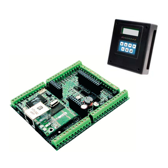
Smartcat (BL2100)
C-Programmable Single-Board Computer with Ethernet
and Operator Interface
User's Manual
019–0103_M
Table of
Contents
Previous
Page
Next
Page
1
2
3
4
5
Advertisement
Table of Contents
Need help?
Do you have a question about the Smartcat and is the answer not in the manual?
Ask a question
Questions and answers
Related Manuals for Rabbit Smartcat
Motherboard Rabbit BL2100 User Manual
C-programmable single-board computer with ethernet and operator interface (135 pages)
Motherboard Rabbit Wildcat BL2000 User Manual
C-programmable single-board computer with ethernet (94 pages)
Motherboard Rabbit BL4S200 User Manual
C-programmable single-board computer with networking (213 pages)
Motherboard Rabbit Fox LP3500 User Manual
C-programmable single-board computer (143 pages)
Motherboard Rabbit BL2600 User Manual
Bl2600 series c-programmable single-board computer with ethernet (116 pages)
Motherboard Rabbit Wildcat BL2010 User Manual
C-programmable single-board computer with ethernet (95 pages)
Motherboard Rabbit Coyote BL2500 User Manual
C-programmable, with ethernet (107 pages)
Motherboard Rabbit 101-1147 Getting Started
Rio programmable i/o kit (4 pages)
Motherboard Rabbit BL4S100 Product Manual
C-programmable single-board computer with networking (144 pages)
This manual is also suitable for:
Bl2100
Table of Contents
Print
Rename the bookmark
Delete bookmark?
Delete from my manuals?
Login
Sign In
OR
Sign in with Facebook
Sign in with Google
Upload manual
Upload from disk
Upload from URL


Need help?
Do you have a question about the Smartcat and is the answer not in the manual?
Questions and answers