
Related Manuals for Rabbit BL4S100


Summary of Contents for Rabbit BL4S100
- Page 1 BL4S100 C-Programmable Single-Board Computer with Networking User’s Manual 019–0172_C Downloaded from Elcodis.com electronic components distributor...
- Page 2 Rabbit, RabbitCore, and Dynamic C are registered trademarks of Digi International Inc. RabbitNet is a trademark of Digi International Inc. The latest revision of this manual is available on the Rabbit Web site, www.rabbit.com, for free, unregistered download. Digi International Inc.
-
Page 3: Table Of Contents
2.2 Installing Dynamic C ..........................13 2.3 Starting Dynamic C ..........................14 2.4 Run a Sample Program ........................14 2.4.1 Troubleshooting ..........................14 2.4.2 Run a ZigBee Sample Program (BL4S100/BL4S150 only) ............15 2.5 Where Do I Go From Here? .......................16 Chapter 3. Subsystems 3.1 BL4S100 Pinouts ..........................18 3.1.1 Connectors ..........................18... - Page 4 A.1 Electrical and Mechanical Specifications ..................113 A.1.1 Exclusion Zone.........................115 A.1.2 Headers.............................115 A.2 Jumper Configurations........................116 A.3 Use of Rabbit Microprocessor Parallel Ports...................118 Appendix B. Power Supply B.1 Power Supplies..........................120 B.2 Batteries and External Battery Connections ..................121 B.2.1 Replacing the Backup Battery ....................121 Appendix C.
- Page 5 F.1 XBee Module Firmware Downloads ....................134 F.1.1 Dynamic C v. 10.44 and Later ....................134 ® F.2 Digi XBee USB Configuration ......................135 F.2.1 Additional Reference Information ....................136 ® F.2.2 Update Digi XBee USB Firmware ..................138 Index Schematics BL4S100 User’s Manual Downloaded from Elcodis.com electronic components distributor...
-
Page 6: Chapter 1. Introduction
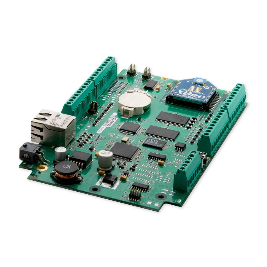
4000 microprocessor provides fast data processing. 1.1 BL4S100 Description Throughout this manual, the term BL4S100 refers to the complete series of BL4S100 single- board computers unless other production models are referred to specifically. The BL4S100 is an advanced single-board computer that incorporates the powerful Rabbit 4000 microprocessor, serial flash memory, static RAM, digital inputs, digital outputs, A/D converter inputs, RS-232 serial ports, and Ethernet and ZigBee network connectivity. - Page 7 • Battery-backed real-time clock. • Watchdog supervisor. Four BL4S100 models are available. Their standard features are summarized in Table 1. Table 1. BL4S100 Models Feature BL4S100 BL4S110 BL4S150 BL4S160 ® Microprocessor Rabbit 4000 running at 40.00 MHz Program Execution SRAM...
-
Page 8: Development And Evaluation Tools
1.3 Development and Evaluation Tools 1.3.1 Tool Kit A Tool Kit contains the hardware essentials you will need to use your own BL4S100 single- board computer. These items are supplied in the Tool Kit. • Getting Started instructions. • Dynamic C CD-ROM, with complete product documentation on disk. -
Page 9: Software
1.3.2 Software The BL4S100 is programmed using version 10.44 or later of Rabbit’s Dynamic C. A com- This version of Dynamic C includes the patible version is included on the Tool Kit CD-ROM. popular µC/OS-II real-time operating system, point-to-point protocol (PPP), FAT file... -
Page 10: Ce Compliance
These limits apply over the range of 30–230 MHz. The limits are 7 dB higher for frequen- cies above 230 MHz. Although the test range goes to 1 GHz, the emissions from Rabbit- based systems at frequencies above 300 MHz are generally well below background noise levels. -
Page 11: Design Guidelines
• When connecting the BL4S100 single-board computer to outdoor cables, the customer is responsible for providing CE-approved surge/lighting protection. • Rabbit recommends placing digital I/O or analog cables that are 3 m or longer in a metal conduit to assist in maintaining CE compliance and to conform to good cable design practices. -
Page 12: Chapter 2. Getting Started
2. G ETTING TARTED Chapter 2 explains how to connect the programming cable and power supply to the BL4S100. BL4S100 User’s Manual Downloaded from Elcodis.com electronic components distributor... -
Page 13: Bl4S100 Connections
PROG connector of the programming cable to header J8 on the BL4S100. Ensure that the colored edge lines up with pin 1 as shown. (Do not use the DIAG connector, which is used for monitoring only.) Connect the other end of the programming cable to an available USB port on your PC or workstation. -
Page 14: Hardware Reset
Release the clip to secure the plug assembly in the AC adapter. Connect the power supply to header J17 on the BL4S100 as shown in Figure 3. Be sure to match the latch mechanism with the top of the connector to header J17 on the BL4S100 as shown. -
Page 15: Installing Dynamic C
If you have not yet installed Dynamic C version 10.44 (or a later version), do so now by inserting the Dynamic C CD from the BL4S100 Tool Kit in your PC’s CD-ROM drive. If autorun is enabled, the CD installation will begin automatically. -
Page 16: Starting Dynamic C
If the LED is lit, check both ends of the programming cable to ensure that it is firmly plugged into the PC and the programming header on the BL4S100 with the marked (col- ored) edge of the programming cable towards pin 1 of the programming header. -
Page 17: Run A Zigbee Sample Program (Bl4S100/Bl4S150 Only)
(BL4S100/BL4S150 only) 2.4.2 Run a ZigBee Sample Program This section explains how to run a sample program in which the BL4S100/BL4S150 is used ® in its default setup as a router and the Digi XBee USB is used as the ZigBee coordinator. -
Page 18: Where Do I Go From Here
• Use the Technical Support e-mail form at www.rabbit.com/support/. If the sample program ran fine, you are now ready to go on to explore other BL4S100 features and develop your own applications. When you start to develop an application involving the analog inputs, run... -
Page 19: Chapter 3. Subsystems
3. S UBSYSTEMS Chapter 3 describes the principal subsystems for the BL4S100. • Digital I/O • Serial Communication • A/D Converter Inputs • Memory Figure 4 shows these Rabbit-based subsystems designed into the BL4S100. BL4S100 Programming Port Digital Real-Time Main... -
Page 20: Bl4S100 Pinouts
Figure 5. BL4S100 Pinouts 3.1.1 Connectors Standard BL4S100 models are equipped with an RJ-45 Ethernet jack, four 1 × 9 screw- terminal headers and one 1 × 6 screw-terminal header for the I/O and RS-232 signals. The polarized 2 × 2 Micro-Fit ®... -
Page 21: Digital I/O
3.2 Digital I/O 3.2.1 Digital Inputs The BL4S100 has 12 digital inputs, IN0–IN11, each of which is protected over a range of –36 V to +36 V. The inputs are factory-configured to be pulled up to +5 V, but they can also be pulled up to +K or pulled down to 0 V by changing a jumper as shown in Figure 6. - Page 22 The use of these channels for interrupts, input capture, and as quadrature decoders is described below. Blocks of digital input pins are associated with counters/timers on the Rabbit RIO chip. Table 3 provides complete details for these associations.
- Page 23 3.2.1.1 Interrupt, Counter, and Event Capture Setup External interrupts on the BL4S100 digital input pins are configured using the setEx- function call. The interrupt can be set up to occur on a rising edge, a fall- tInterrupt() ing edge, or either edge.
-
Page 24: Digital Outputs
All the digital outputs sink actively. They can be used as low-side drivers, or as an H-bridge driver. When the BL4S100 is first powered up or reset, all the outputs are disabled, that is, at a high-impedance state. - Page 25 Blocks of digital output pins are associated with counters/timers on the Rabbit RIO chip. Table 4 provides complete details for these associations. Table 4. Counter/Timer Associations for BL4S100 Digital Output Pins Configurable I/O Counter/Timer Block Shared With Pin(s) Blocks OUT0–OUT1 IN6–IN7...
- Page 26 PPM Shifted Offset outputs are on the same block of a particu- lar Rabbit RIO chip PWM and PPM outputs on the BL4S100 are configured using the setPWM() function calls. setPPM() BL4S100 User’s Manual Downloaded from Elcodis.com...
-
Page 27: Serial Communication
PC while a program is being debugged. The Rabbit 4000 startup-mode pins (SMODE0, SMODE1) are presented to the program- ming port so that an externally connected device can force the BL4S100 to start up in an BL4S100 User’s Manual Downloaded from Elcodis.com... -
Page 28: Ethernet Port
The BL4S100 can be reset from the programming port via the line. /RESET_IN The Rabbit microprocessor status pin is also presented to the programming port. The status pin is an output that can be used to send a general digital signal. -
Page 29: A/D Converter Inputs
3.4 A/D Converter Inputs The single A/D converter chip used in the BL4S100 has a resolution of 12 bits (11 bits for the value and one bit for the polarity). The A/D converter chip has a programmable-gain amplifier. Each external input has circuitry that provides scaling and filtering. All 8 external inputs are scaled and filtered to provide the user with an input impedance of 1 M... - Page 30 100 AIN2 resistor. 100 W AIN3 Figure 12. Analog Current Measurements The A/D converter inputs are factory-calibrated, and the calibration constants are stored in the user block. BL4S100 User’s Manual Downloaded from Elcodis.com electronic components distributor...
-
Page 31: A/D Converter Calibration
ADC_CAL_DIFF.C 4–20 mA ADC_RD_MA.C ADC_CAL_MA.C These sample programs are found in the subdirectory in . See SAMPLES\BL4S1xx Section 4.2.3 for more information on these sample programs and how to use them. BL4S100 User’s Manual Downloaded from Elcodis.com electronic components distributor... -
Page 32: Usb Programming Cable
The USB programming cable is used to connect the serial programming port of the BL4S100 to a PC USB port. The programming cable converts the voltage levels used by the PC USB port to the CMOS voltage levels used by the Rabbit microprocessor. -
Page 33: Other Hardware
3.6 Other Hardware 3.6.1 Clock Doubler The BL4S100 takes advantage of the Rabbit microprocessor’s internal clock doubler. A built-in clock doubler allows half-frequency crystals to be used to reduce radiated emissions. The clock doubler may be disabled if the higher clock speeds are not required. Disabling the clock doubler will reduce power consumption and further reduce radiated emissions. -
Page 34: Memory
3.7 Memory 3.7.1 SRAM All BL4S100 boards have 512KB of battery-backed data SRAM, and 512KB–1MB of fast program execution SRAM. 3.7.2 Flash Memory BL4S100 boards have 1MB—2MB of serial flash memory. Writing to arbitrary flash memory addresses at run time is also discouraged. Instead, define a “user block”... -
Page 35: Chapter 4. Software
Chapter 4 provides the libraries, function calls, and sample pro- grams related to the BL4S100. 4.1 Running Dynamic C Since the BL4S100 has a serial flash memory, all software development must be done in the static SRAM. The flash memory and SRAM options are selected with the Options >... - Page 36 LCD display and keypad drivers. • Powerful language extensions for cooperative or preemptive multitasking • Loader utility program to load binary images into Rabbit targets in the absence of Dynamic C. • Provision for customers to create their own source code libraries and augment on-line help by creating “function description”...
-
Page 37: Upgrading Dynamic C
The default installation of a patch or update is to install the file in a directory (folder) different from that of the original Dynamic C installation. Rabbit recommends using a different directory so that you can verify the operation of the patch or update without over- writing the existing Dynamic C installation. -
Page 38: Sample Programs
. The BL4S100 must be in Program mode (see Section 3.5, “USB Programming Cable,”) and must be connected to a PC using the programming cable as described in Section 2.1, “BL4S100 Connections.” See Appendix C for information on the power-supply connections to the Demonstration Board. -
Page 39: Digital I/O
Demonstration Board, you can see an input channel toggle from HIGH to LOW in the Dynamic C STDIO window when you press a pushbutton on the Demonstration Board. The banking functions allow I/O banks to be input or output more efficiently. BL4S100 User’s Manual Downloaded from Elcodis.com electronic components distributor... - Page 40 Using the Demonstration Board, you can see an LED toggle on/off via a sinking output that you selected via the Dynamic C window. The banking func- STDIO tions allow I/O banks to be input or output more efficiently. BL4S100 User’s Manual Downloaded from Elcodis.com electronic components distributor...
- Page 41 #define PPM_FREQ instructions when running this sample program. 1. The digital outputs on the BL4S100 do not have an internal pull-up resistor and will not register on the oscilloscope without a pull-up resistor. The Demonstration Board has pull-up resistors— connect OUT0–OUT3 on the BL4S100 to SW1–SW4 on header J1 of the Demonstration Board.
- Page 42 Follow these instructions when running this sample program. #define PWM_FREQ 1. The digital outputs on the BL4S100 do not have an internal pull-up resistor and will not register on the oscilloscope without a pull-up resistor. The Demonstration Board has pull-up resistors—...
- Page 43 —Demonstrates the use of quadrature decoders on the • QUADRATURE_DECODER.C BL4S100. See Figure 16 for hookup instructions of the digital I/O pins on headers J3 and J4 with the Demonstration Board. JP15 DIGITAL I/O HEADER J3 BL4S100 IN0 + OUT0...
- Page 44 PPM_QUADRATURE_DECODER.C output channels connected back to four digital inputs to simulate two Quadrature Decoders feeding signals into the BL4S100. The PWM and PPM outputs are adjusted through a menu system to simulate the movement of a Quadrature Decoder. The results of the Quadrature Decoder inputs are displayed continuously to show the effects of the PWM and PPM outputs.
-
Page 45: Serial Communication
RTS and CTS are connected again. —This sample program demonstrates using parity over a simple • COMPUTER_PARITY.C three-wire RS-232 connection. Parity is selected for the BL4S100 and for the serial ter- minal emulation program. Characters typed in either the Dynamic C window or STDIO in the serial terminal emulation program are echoed in both displays. - Page 46 There may be some differences for special characters such as new lines (enter key), delete, backspace, and others. Each character sent will also increment either the successful or the error counter, depending on the parity of both the BL4S100 and the terminal emulation program.
-
Page 47: A/D Converter Inputs
OFF) between the pin (AIN0–AIN7) of an analog input channel and AGND, then compile and run the sample program, and follow the instructions in the Dynamic C STDIO window. BL4S100 User’s Manual Downloaded from Elcodis.com electronic components distributor... -
Page 48: Real-Time Clock
4.2.5 TCP/IP Sample Programs TCP/IP sample programs are described in Chapter 5. 4.2.6 ZigBee Sample Programs ZigBee sample programs are described in Chapter 6. BL4S100 User’s Manual Downloaded from Elcodis.com electronic components distributor... -
Page 49: Bl4S100 Libraries
4.3 BL4S100 Libraries Two library directories provide libraries of function calls that are used to develop applica- tions for the BL4S100. —libraries associated with features specific to the BL4S100. The functions in • BL4S1xx library are described in Section 4.4, “BL4S100 Function Calls.”... -
Page 50: Bl4S100 Function Calls
(void); FUNCTION DESCRIPTION Call this function at the beginning of your program. This function initializes Parallel Ports A–E, the Rabbit RIO chip, and the A/D converter. The ports are initialized according to Table A-3 in Appendix A. BL4S100 User’s Manual Downloaded from Elcodis.com... -
Page 51: Digital I/O
The logic state of the specified channel. 0 — logic low 1 — logic high — channel value is out of range. -EINVAL :— channel functionality does not permit this operation. -EPERM SEE ALSO brdInit, setDigIn, digInBank BL4S100 User’s Manual Downloaded from Elcodis.com electronic components distributor... - Page 52 1 — IN8–IN11 RETURN VALUE Data read from the bank of digital inputs. Data Bits Bank 0 Bank 1 IN10 IN11 not used — invalid parameter value. -EINVAL SEE ALSO brdInit, digIn, setDigIn BL4S100 User’s Manual Downloaded from Elcodis.com electronic components distributor...
- Page 53 Appendix D provides the details of the pin and block associations to allow you to identify the channels that need to be reconfigured to support this function call. SEE ALSO brdInit, digIn, setDigIn BL4S100 User’s Manual Downloaded from Elcodis.com electronic components distributor...
- Page 54 — index on high level RETURN VALUE 0 — success. — invalid parameter value. -EINVAL — resource needed by this function is not available. -EACCESS SEE ALSO brdInit, getCounter, resetCounter BL4S100 User’s Manual Downloaded from Elcodis.com electronic components distributor...
- Page 55 ORed together. The low 4 bits are the channel num- ber for the down count input If the mode is selected, has the BL_MATCH_ENABLE options match count to stop at (other match registers on the block are set to max.). BL4S100 User’s Manual Downloaded from Elcodis.com electronic components distributor...
- Page 56 Appendix D provides the details of the pin and block associations to allow you to identify the channels that need to be reconfigured to support this function call. SEE ALSO brdInit, getCounter, resetCounter BL4S100 User’s Manual Downloaded from Elcodis.com electronic components distributor...
- Page 57 — begin event on any edge BL_EVENT_BOTH The following two settings are only for the BL_CNT_ON_BEGIN mode: — begin active while signal is high BL_BEGIN_HIGH — begin active while signal is low BL_BEGIN_LOW BL4S100 User’s Manual Downloaded from Elcodis.com electronic components distributor...
- Page 58 Appendix D provides the details of the pin and block associations to allow you to identify the channels that need to be reconfigured to support this function call. SEE ALSO brdInit, getBegin, getEnd, getCounter, resetCounter BL4S100 User’s Manual Downloaded from Elcodis.com electronic components distributor...
- Page 59 RETURN VALUE 0 — success. — invalid parameter value. -EINVAL — pin type does not permit this function. -EPERM SEE ALSO brdInit, setCapture, resetCounter, getEnd BL4S100 User’s Manual Downloaded from Elcodis.com electronic components distributor...
- Page 60 0–11 (pins IN0–IN11) RETURN VALUE 0 — success. — invalid parameter value. -EINVAL — pin type does not permit this function. -EPERM SEE ALSO brdInit, getCounter, setDecoder BL4S100 User’s Manual Downloaded from Elcodis.com electronic components distributor...
- Page 61 RETURN VALUE 0 — success. — invalid parameter value. -EINVAL — pin type does not permit this function. -EPERM SEE ALSO brdInit, setCapture, resetCounter BL4S100 User’s Manual Downloaded from Elcodis.com electronic components distributor...
- Page 62 — invalid parameter value. -EINVAL — pin type does not permit this function. -EPERM — resource needed by this function is not available. -EACCES — internal data fault detected. -EFAULT SEE ALSO brdInit, setSyncOut BL4S100 User’s Manual Downloaded from Elcodis.com electronic components distributor...
- Page 63 (main or prescale). This means synchronized blocks may have a small offset when compared to each other. RETURN VALUE 0 — success. — was not run before calling this function. -EPERM brdInit() SEE ALSO brdInit BL4S100 User’s Manual Downloaded from Elcodis.com electronic components distributor...
- Page 64 0 — connects the load to GND 1 — puts the output in a high-impedance state RETURN VALUE 0 — success. — invalid parameter value. -EINVAL SEE ALSO brdInit, digOut, digOutBank BL4S100 User’s Manual Downloaded from Elcodis.com electronic components distributor...
- Page 65 1 — puts the output in a high-impedance state. RETURN VALUE 0 — success. — invalid parameter value. -EINVAL — pin function was not set up as a digital output -EPERM SEE ALSO brdInit, setDigOut, digOutBank BL4S100 User’s Manual Downloaded from Elcodis.com electronic components distributor...
- Page 66 0 — connects the load to GND 1 — puts the output in a high-impedance state. RETURN VALUE 0 — success. — invalid parameter value or board not initialized. -EINVAL SEE ALSO brdInit, digOut, setDigOut BL4S100 User’s Manual Downloaded from Elcodis.com electronic components distributor...
- Page 67 PWM output on this channel. Bindings allow PWM and PPM outputs to align their leading and trailing edges. BL4S100 User’s Manual Downloaded from Elcodis.com...
- Page 68 Appendix D provides the details of the pin and block associations to allow you to identify the channels that need to be reconfigured to support this function call. SEE ALSO brdInit, setFreq, setDuty, setSyncIn, setSyncOut, pulseEnable, pulseDisable, setPPM BL4S100 User’s Manual Downloaded from Elcodis.com electronic components distributor...
- Page 69 PPM output on this channel. Bindings allow PWM and PPM outputs to align their leading and trailing edges BL4S100 User’s Manual Downloaded from Elcodis.com electronic components distributor...
- Page 70 Appendix D provides the details of the pin and block associations to allow you to identify the channels that need to be reconfigured to support this function call. SEE ALSO brdInit, setFreq, setOffset, setDuty, setSyncIn, setSyncOut, pulseEnable, pulseDisable, setPWM BL4S100 User’s Manual Downloaded from Elcodis.com electronic components distributor...
- Page 71 50 kHz). Use -1 to preserve the existing frequency on the RIO block. RETURN VALUE 0 — success. — invalid parameter value. -EINVAL SEE ALSO brdInit, setPWM, setPPM, setOffset, setDuty, setSyncIn, setSyncOut, pulseEnable, pulseDisable BL4S100 User’s Manual Downloaded from Elcodis.com electronic components distributor...
- Page 72 RETURN VALUE 0 — success. — invalid parameter value. -EINVAL — channel function does not permit this operation. -EPERM SEE ALSO brdInit, setPWM, setPPM, setOffset, setFreq, setSyncIn, setSyncOut, pulseEnable, pulseDisable BL4S100 User’s Manual Downloaded from Elcodis.com electronic components distributor...
- Page 73 RETURN VALUE 0 — success. — invalid parameter value. -EINVAL — channel function does not permit this operation. -EPERM SEE ALSO brdInit, setPWM, setPPM, setFreq, setDuty, setSyncIn, setSyncOut, pulseEnable, pulseDisable BL4S100 User’s Manual Downloaded from Elcodis.com electronic components distributor...
- Page 74 PWM/PPM enabled, channel 0–7 (OUT0–OUT7) RETURN VALUE 0 — success. — invalid parameter value. -EINVAL — channel function does not permit this operation. -EPERM SEE ALSO brdInit, setPWM, setPPM, pulseDisable BL4S100 User’s Manual Downloaded from Elcodis.com electronic components distributor...
- Page 75 — invalid parameter value. -EINVAL — pin type does not permit this function. -EPERM — resource needed by this function is not available. -EACCES — internal data fault detected. -EFAULT SEE ALSO brdInit, setSyncIn BL4S100 User’s Manual Downloaded from Elcodis.com electronic components distributor...
- Page 76 Match Register 1 BL_IER_MATCH1 bit set if using Match Register 2 BL_IER_MATCH2 bit set if using Match Register 3 BL_IER_MATCH3 — invalid channel value. -EINVAL SEE ALSO brdInit, setPWM, setPPM, setCounter BL4S100 User’s Manual Downloaded from Elcodis.com electronic components distributor...
-
Page 77: Rabbit Rio Interrupt Handlers
4.4.3 Rabbit RIO Interrupt Handlers addISRIn int addISRIn(int channel, int ier, void (*handler)()); FUNCTION DESCRIPTION Adds an interrupt handler for the interrupts specified in the parameter for the given RIO block hosting the given configurable I/O pin. The interrupt service routine (ISR) is always disabled when created. - Page 78 RETURN VALUE Success — returns the handler ID number ( 0..RSB_MAX_ISR-1 — Invalid parameter given. -EINVAL — No more room in ISR table (increase -ENOSPC RSB_MAX_ISR SEE ALSO addISRIn, tickISR, enableISR, setIER BL4S100 User’s Manual Downloaded from Elcodis.com electronic components distributor...
- Page 79 (bit positions match RIO Interrupt Enable and Status registers) RETURN VALUE 0 — success — Invalid parameter given. -EINVAL — Handler is enabled, can't change IER. -EPERM SEE ALSO addISRIn, addISROut, enableISR, tickISR BL4S100 User’s Manual Downloaded from Elcodis.com electronic components distributor...
- Page 80 Polls the RIO chip(s) for ISR events if interrupts are not being used. Any enabled ISR events will be passed to the appropriate ISR handler. RETURN VALUE None. SEE ALSO addISRIn, addISROut, enableISR, setIER BL4S100 User’s Manual Downloaded from Elcodis.com electronic components distributor...
-
Page 81: Serial Communication
For more information, see the Dynamic C User’s Manual and Technical Note 213, Rabbit Serial Port Software. Use the following function calls with the BL4S100. serMode int serMode(int mode);... -
Page 82: A/D Converter Inputs
— single-ended unipolar (0–20 V) SE0_MODE — differential bipolar (±20 V) DIFF_MODE — 4–20 mA operation mAMP_MODE RETURN VALUE: 0 — success. — invalid parameter. -EINVAL SEE ALSO brdInit, anaInCalib, anaIn, anaInVolts, anaInmAmps, anaInDiff BL4S100 User’s Manual Downloaded from Elcodis.com electronic components distributor... - Page 83 Use one of the opmode following macros to set the mode for the channel being configured. = single-ended unipolar (0–20 V) SE0_mode = differential bipolar (±20 V) DIFF_MODE = 4–20 mA mAMP_mode BL4S100 User’s Manual Downloaded from Elcodis.com electronic components distributor...
- Page 84 A/D converter value volts2 RETURN VALUE 0 — success. — invalid parameter. -EINVAL — error writing calibration constants. -ERR_ANA_CALIB SEE ALSO brdInit, anaInConfig, anaIn, anaInmAmps, anaInDiff, anaInVolts BL4S100 User’s Manual Downloaded from Elcodis.com electronic components distributor...
- Page 85 0–2.5 V ± 2.5 V 0–2.5 V GAIN_X8 0–2 V ± 2 V 0–2 V GAIN_X10 GAIN_X16 0–1.25 V ± 1.25 V 0–1.25 V 0–1 V ± 1 V 0–1 V GAIN_X20 BL4S100 User’s Manual Downloaded from Elcodis.com electronic components distributor...
- Page 86 BL_OVERFLOW BL_WRONG_MODE System errors (can create run-time error unless disabled): — fault detected in reading calibration factor -ERR_ANA_CALIB — invalid parameter value. -ERR_ANA_INVAL SEE ALSO brdInit, anaInConfig, anaInCalib, anaInmAmps, anaInDiff, anaInVolts BL4S100 User’s Manual Downloaded from Elcodis.com electronic components distributor...
- Page 87 0–2.5 V ± 2.5 V 0–2.5 V GAIN_X8 GAIN_X10 0–2 V ± 2 V 0–2 V 0–1.25 V ± 1.25 V 0–1.25 V GAIN_X16 0–1 V ± 1 V 0–1 V GAIN_X20 BL4S100 User’s Manual Downloaded from Elcodis.com electronic components distributor...
- Page 88 BL_WRONG_MODE anaInConfig() System errors (can create run-time error unless disabled): — fault detected in reading calibration facto.r -ERR_ANA_CALIB — invalid parameter value. -ERR_ANA_INVAL SEE ALSO brdInit, anaInConfig, anaIn, anaInmAmps, anaInDiff, anaInCalib BL4S100 User’s Manual Downloaded from Elcodis.com electronic components distributor...
- Page 89 0–4 V GAIN_X5 ×8 ± 2.5 V 0–2.5 V GAIN_X8 ×10 ± 2 V 0–2 V GAIN_X10 ×16 ± 1.25 V 0–1.25 V GAIN_X16 GAIN_X20 ×20 ± 1 V 0–1 V BL4S100 User’s Manual Downloaded from Elcodis.com electronic components distributor...
- Page 90 BL_WRONG_MODE anaInConfig() System errors (can create run-time error unless disabled): — fault detected in reading calibration factor. -ERR_ANA_CALIB — invalid parameter value. -ERR_ANA_INVAL SEE ALSO brdInit, anaInConfig, anaIn, anaInmAmps, anaInVolts, anaInCalib BL4S100 User’s Manual Downloaded from Elcodis.com electronic components distributor...
- Page 91 BL_WRONG_MODE anaInConfig() System errors (can create run-time error unless disabled): — fault detected in reading calibration factor. -ERR_ANA_CALIB — invalid parameter value. -ERR_ANA_INVAL SEE ALSO brdInit, anaInConfig, anaIn, anaInDiff, anaInVolts, anaInCalib BL4S100 User’s Manual Downloaded from Elcodis.com electronic components distributor...
- Page 92 ±4 V GAIN_X5 0–2.5 V ±2.5 V GAIN_X8 GAIN_X10 0–2 V ±2 V 0–1.25 V ±1.25 V GAIN_X16 0–1 V ±1 V GAIN_X20 calibration structure pointer to gain and offset values pcal_data BL4S100 User’s Manual Downloaded from Elcodis.com electronic components distributor...
- Page 93 -1 — invalid address or range. -2 — no valid user block found (block version 3 or later) -3 — flash read error — invalid parameter -EINVAL SEE ALSO anaInCalib, _anaInAddr BL4S100 User’s Manual Downloaded from Elcodis.com electronic components distributor...
- Page 94 MSB is set high for direct-mode access. The format is as follows: D6–D4 D3–D0 gain_code channel_code Use the following calculation and tables to determine cmd = 0x80 | (gain_code<<4) + channel_code Multiplier gain_code BL4S100 User’s Manual Downloaded from Elcodis.com electronic components distributor...
- Page 95 — conversion incomplete, busy bit timeout BL_TIMEOUT — overflow or out of range BL_OVERFLOW System errors (can create run-time error unless disabled): — invalid parameter value -ERR_ANA_INVAL SEE ALSO anaInConfig, anaIn, brdInit BL4S100 User’s Manual Downloaded from Elcodis.com electronic components distributor...
-
Page 96: Sram Use
4.4.6 SRAM Use The BL4S100 has a battery-backed data SRAM and a program-execution SRAM. Dynamic C provides the keyword to identify variables that are to be placed protected into the battery-backed SRAM. The compiler generates code that maintains two copies of each protected variable in the battery-backed SRAM. -
Page 97: Chapter 5. Using The Ethernet Tcp/Ip Features
• Two RJ-45 straight-through CAT 5/6 Ethernet cables and a hub, or an RJ-45 crossover CAT 5/6 Ethernet cable. The CAT 5/6 Ethernet cables and Ethernet hub are available from Rabbit in a TCP/IP tool kit. More information is available at www.rabbit.com. - Page 98 Direct Connection Using a Hub (network of 2 computers) Figure 17. Ethernet Connections The PC running Dynamic C through the serial programming port on the BL4S100 does not need to be the PC with the Ethernet card. 3. Apply Power Plug in the AC adapter.
-
Page 99: Tcp/Ip Sample Programs
These programs require that you connect your PC and the BL4S100 together on the same network. This network can be a local private network (pre- ferred for initial experimentation and debugging), or a connection via the Internet. -
Page 100: How To Set Up Your Computer For Direct Connect
Default gateway : 10.10.6.1 4. Click <OK> <Close> to exit the various dialog boxes. BL4S100 Board IP 10.10.6.101 Netmask 255.255.255.0 User’s PC crossover CAT 5/6 Ethernet cable Direct Connection PC to BL4S100 BL4S100 User’s Manual Downloaded from Elcodis.com electronic components distributor... -
Page 101: Run The Pingme.c Demo
5.2.3 Run the PINGME.C Demo Connect the crossover cable from your computer’s Ethernet port to the BL4S100’s RJ-45 Ethernet connector. Open this sample program from the folder, SAMPLES\TCPIP\ICMP compile the program, and start it running under Dynamic C. When the program starts run-... -
Page 102: Running More Demo Programs With A Direct Connection
• RWEB_DIGITAL_OUTPUTS.C digOut() control the sinking digital outputs on the BL4S100 to toggle the LEDs on the Demon- stration Board on/off. Once the sample program is compiled and running, open your PC Web browser. As long as you have not modified the... - Page 103 Now use a wire to touch +5 V from header J4 on the BL4S100 to the various digital and analog inputs on header J3, J15, and J16 —Uses the SMTP library to send an e-mail when a pushbutton switch on the •...
-
Page 104: Where Do I Go From Here
5.3 Where Do I Go From Here? NOTE: If you purchased your BL4S100 through a distributor or Rabbit partner, contact the distributor or partner first for technical support. If there are any problems at this point: • Use the Dynamic C Help menu to get further assistance with Dynamic C. -
Page 105: Chapter 6. Using The Zigbee Features
IEEE 802.15.4 stan- dard for wireless personal area networks (WPANs). The XBee RF module used by the BL4S100 and the BL4S150 operates in the 2.4 GHz industrial, scientific, and medical (ISM) radio band in most jurisdictions worldwide. -
Page 106: Zigbee Sample Programs
In order to run the sample programs discussed in this chapter and elsewhere in this manual, 1. Dynamic C must be installed and running on your PC. 2. The programming cable must connect the programming header on the BL4S100 or the BL4S150 to your PC. -
Page 107: Setting Up The Digi Xbee Usb Coordinator
1. Connect the Digi XBee USB acting as a ZigBee coordinator to an available USB port on your PC or workstation. Your PC should recognize the new USB hardware. 2. Connect the Demonstration Board to the BL4S100 as shown below. JP15 DIGITAL OUTPUTS OUT0 OUT0–OUT3... - Page 108 Digi XBee USB and recompile the sample program once you make sure the BL4S100/BL4S150 is powered up. The timeout may occur if you are doing develop- ment simultaneously with more than one ZigBee coordinator. Appendix F explains the ®...
-
Page 109: Setting Up Sample Programs
Try pinging the selected device by clicking the “Send Ping” button. 6.2.2 Setting up Sample Programs The sample programs are set up so that the BL4S100/Bl4S150 you are using is a ZigBee router, coordinator, or end device. Uncomment the line corresponding to the role the BL4S100/Bl4S150 will have once it is running the sample program. - Page 110 AT commands. Several commands can either set a parameter or read it. This sample program simply reads the parameters and displays the results. Compile and run this sample program. The program will display the results in the Dynamic C STDIO window. BL4S100 User’s Manual Downloaded from Elcodis.com electronic components distributor...
- Page 111 Utilities\XBee GPIO GUI folder) on your PC. Configure the GUI client to connect to the Digi USB XBee coordi- nator and scan for devices. Make sure the BL4S100/BL4S150 and the Digi USB XBee coordinator are configured with the same PAN ID.
- Page 112 You can use the Web browser to control the boards. Note that the XB24-ZB_2x40 firmware allows you to set digital outputs on all node types, but analog and digital inputs can only be read on end devices. BL4S100 User’s Manual Downloaded from Elcodis.com electronic components distributor...
-
Page 113: Dynamic C Function Calls
Introduction to ZigBee, which is included in the online documentation set. 6.4 Where Do I Go From Here? NOTE: If you purchased your BL4S100/BL4S150 through a distributor or through a Rabbit partner, contact the distributor or partner first for technical support. -
Page 114: Appendix A. Specifications
A. S PPENDIX PECIFICATIONS Appendix A provides the specifications for the BL4S100. BL4S100 User’s Manual Downloaded from Elcodis.com electronic components distributor... -
Page 115: Electrical And Mechanical Specifications
A.1 Electrical and Mechanical Specifications Figure A-1 shows the mechanical dimensions for the BL4S100. 0.125 dia × 4 (3.2) 0.375 0.497 (9.5) (12.6) RJ-45 jack extends 0.12" (3.1 mm) past edge of R26 R34 board ® Micro-Fit connector R48 R49 extends 0.11"... - Page 116 Table A-1 lists the electrical, mechanical, and environmental specifications for the BL4S100. Table A-1. BL4S100 Specifications Feature BL4S100 BL4S110 BL4S150 BL4S160 ® Microprocessor Rabbit 4000 at 40.00 MHz Ethernet Interface 10Base-T ZigBee PRO ZigBee PRO ZigBee Interface — — (802.15.4) (802.15.4)
-
Page 117: Exclusion Zone
It is recommended that you allow for an “exclusion zone” of 0.25" (6 mm) around the BL4S100 in all directions when the BL4S100 is incorporated into an assembly that includes other components. This “exclusion zone” that you keep free of other components and boards will allow for sufficient air flow, and will help to minimize any electrical or EMI interference between adjacent boards. -
Page 118: Jumper Configurations
A.2 Jumper Configurations Figure A-3 shows the header locations used to configure the various BL4S100 options via jumpers. Battery Figure A-3. Location of BL4S100 Configurable Positions Table A-2 lists the configuration options. Table A-2. BL4S100 Jumper Configurations Factory Header Description... - Page 119 Table A-2. BL4S100 Jumper Configurations (continued) Factory Header Description Pins Connected Default × None Voltage Option A/D Converter Voltage/Current 1–2 AIN2 4–20 mA option Measurement Options 5–6 AIN3 4–20 mA option × None Voltage Option A/D Converter Voltage/Current 1–2 AIN0 4–20 mA option Measurement Options 5–6 AIN1 4–20 mA option...
-
Page 120: Use Of Rabbit Microprocessor Parallel Ports
A.3 Use of Rabbit Microprocessor Parallel Ports Table A-3 lists the Rabbit microprocessor parallel ports and their use in the BL4S100 boards. Table A-3. Use of Rabbit Microprocessor Parallel Ports Port Signal Initial State PA0–PA7 Rabbit RIO D0–D7 Bus data line... - Page 121 Table A-3. Use of Rabbit Microprocessor Parallel Ports (continued) Port Signal Initial State Output Serial Flash /CS Inactive high Output Ethernet LINK Inactive high (LED off) Output XBee /RTS Output Ethernet ACT Inactive high (LED off) BUFEN Output /CS (A/D converter)
-
Page 122: Appendix B. Power Supply
The input voltage range is from 9 V to 36 V. A switching power regulator is used to provide +5 V for the BL4S100 logic circuits. In turn, the regulated +5 V DC power supply is used to drive regulated +1.8 V and +3.3 V power supplies. -
Page 123: Batteries And External Battery Connections
The drain on the battery is typi- cally less than 10 µA when there is no external power applied to the BL4S100, and so the expected shelf life of the battery is 235 mA·h... -
Page 124: Appendix C. Demonstration Board
C. D PPENDIX EMONSTRATION OARD Appendix C explains how to use the Demonstration Board with the BL4S100 sample programs. BL4S100 User’s Manual Downloaded from Elcodis.com electronic components distributor... -
Page 125: Connecting Demonstration Board
1. Use wires to connect screw-terminal header J3 on the Demonstration Board to header J4 on the BL4S100. The connections are shown in Figure C-1, with the green wire to GND and the blue wire to +V. 2. Make sure that your BL4S100 is connected to your PC via the programming cable and that the power supply is connected to the BL4S100 and plugged in as described in Chapter 2, “Getting Started.”... -
Page 126: Demonstration Board Features
The pushbutton switches may be configured active high or active low via jumper settings on header JP15. ACTIVE LOW JP15 3.3 kW SW1–SW4 ACTIVE HIGH JP15 3.3 kW SW1–SW4 Figure C-3. Pushbutton Switch Configuration BL4S100 User’s Manual Downloaded from Elcodis.com electronic components distributor... - Page 127 +V_ALT location to allow you to vary the voltage at +V_ALT from 0 V to +V. Figure C-5 shows the location of the adjustable output voltage and the potentiometer. Figure C-5. Location of Adjustable Output Voltage BL4S100 User’s Manual Downloaded from Elcodis.com electronic components distributor...
-
Page 128: Appendix D. Rabbit Rio Resource Allocation
ABBIT ESOURCE LLOCATION Appendix D provides the pin and block associations on the Rabbit RIO chip with their corresponding I/O on the BL4S100 boards. The main shared resource within the RIO chips are the counter/timer blocks — the RIO chip has eight counter/timer blocks. A given block is defined by the block number. -
Page 129: Digital I/O Pin Associations
D.1 Digital I/O Pin Associations Table D-1. Digital I/O Pin Associations I/O Pin Block OUT0 OUT1 OUT2 OUT3 OUT4 OUT5 OUT6 OUT7 IN10 IN11 BL4S100 User’s Manual Downloaded from Elcodis.com electronic components distributor... -
Page 130: Interpreting Error Codes
D.2 Interpreting Error Codes Some BL4S100 function calls may return a Mode Conflict error code. This error code is a 4-bit value that identifies other pins using the same counter/timer block on a RIO chip that require this block to be in a mode that conflicts with the functionality that has already been requested —... - Page 131 # — I/O can generally share the timer, but will be affected by settings of the limit value (value at which the timer rolls over) or resetting of the counter, either directly or through synch signals. BL4S100 User’s Manual Downloaded from Elcodis.com...
-
Page 132: Appendix E. Plastic Enclosure
NCLOSURE The plastic enclosure provides a secure way to protect your BL4S100. The enclosure itself may be mounted on any flat surface. The complete plastic enclosure consists of a base and a cover. The base alone is a convenient surface on which to mount the BL4S100, and also provides a means to mount the BL4S100 on any flat surface. -
Page 133: Assembly Instructions
1. Attach the BL4S100 board to the plastic enclosure base. Position the BL4S100 board over the plastic enclosure base as shown below in Figure E-1. Attach the BL4S100 to the base using the four 4-40 × ¼ screws supplied with the enclo- sure base. - Page 134 R26 R34 AIN2 AIN3 R94 R91 C113 C100 R95 R96 C112 ADC PROGRAMMER AIN0 AIN1 R115 AIN0 AIN1 AIN2 AIN3 AIN4 AIN5 AIN6 AIN7 AGND IN11 IN10 Figure E-2. Attach Enclosure Top BL4S100 User’s Manual Downloaded from Elcodis.com electronic components distributor...
-
Page 135: Dimensions
When fully assembled, the total height of the plastic enclosure will be 1.5" (38 mm). NOTE: All measurements are in inches followed by millimeters enclosed in parentheses. All dimensions have a manufacturing tolerance of ±0.01" (0.25 mm). BL4S100 User’s Manual Downloaded from Elcodis.com... -
Page 136: Appendix F. Additional Configuration Instructions
ZigBee coordinator, and how to install the firmware. F.1 XBee Module Firmware Downloads By default, the BL4S100/BL4S150 is shipped from the factory with firmware to operate as a router in a mesh network. You will need to run the MODEMFWLOAD.C sample program in the Dynamic C SAMPLES\XBEE folder to download the firmware needed to operate the BL4S100/BL4S150 as a coordinator or as an end device. -
Page 137: Digi Xbee Usb Configuration
Make the following modifications to the sample program.before you MODEMFWLOAD.C run it according to whether you will be using the BL4S100/BL4S150 as a coordinator, a router, or an end device. • Select the XBee role macro according to whether the BL4S100/BL4S150 is being used as a coordinator, a router or an end-device. -
Page 138: Additional Reference Information
Digi’s Web site for the latest information and documentation on the XBee Series 2 module, the X-CTU utility, and the Digi ® XBee USB. Note that the XBee™ and the XBee BL4S100 User’s Manual Downloaded from Elcodis.com electronic components distributor... - Page 139 PRO™ RF modules are presently not compatible with the XBee Series 2 module used with the BL4S100/BL4S150, but the general documentation about ZigBee and the use of AT commands for the XBee™ and the XBee PRO™ RF modules is relevant.
-
Page 140: Update Digi ® Xbee Usb Firmware
CAUTION: Different firmware versions are likely to interact with the Dynamic C libraries in different ways. Rabbit has tested the firmware associated with a particular version of Dynamic C for correct operation, and only this version is included on the Dynamic C CD-ROM —... - Page 141 ... 22 anaInConfig() ....80 configuration ....135 dimensions anaInDiff() ....87 uploading new firmware . 138 BL4S100 main board ..113 anaInDriver() ....92 digital I/O plastic enclosure ....133 anaInmAmps() ....89 function calls Dynamic C ....7, 33, 34 anaInRdCalib() ....
- Page 142 ADC_CAL_SE_UNIPO- digital I/O ......127 interrupt handlers LAR.C ......45 pinout function calls ADC_RD_CALDATA.C .. BL4S100 headers ....18 addISR() ......75 Demonstration Board ..124 addISROut() ....76 ADC_RD_DIFF.C ..46 Ethernet port ..... 26 enableISR() ....78 ADC_RD_MA.C ..46 plastic enclosure ....
- Page 143 Ethernet port ..... 26 setup ........11 VBAT RAM memory ... 32 power supply connections . 11 software ........7 libraries ......47 BL4S100 ....... 47 XBee module BL4S1xx.LIB ....47 additional resources ..111 PACKET.LIB ....79 firmware download ..134 RS232.LIB ....
-
Page 144: Schematics
CHEMATICS 090-0265 BL4S100 Schematic www.rabbit.com/documentation/schemat/090-0265.pdf 090-0252 USB Programming Cable Schematic www.rabbit.com/documentation/schemat/090-0252.pdf 090-0272 Rabbit Demonstration Board www.rabbit.com/documentation/schemat/090-0272.pdf You may use the URL information provided above to access the latest schematics directly. BL4S100 User’s Manual Downloaded from Elcodis.com electronic components distributor...
Need help?
Do you have a question about the BL4S100 and is the answer not in the manual?
Questions and answers