
Related Manuals for Nexo RS15


Summary of Contents for Nexo RS15
-
Page 1: User Manual
Ray Sub Series RS15 Subwoofer User Manual RaySub Series User Manual V1.01 Date: 10/12/2007... - Page 2 It is now 5 years that NEXO has released its first gradient subwoofer – the CD12 -, complemented since then with the CD18 and the GEO SUB. These have been quickly adopted worldwide as standards, and are considered today as state of the art subwoofers.
- Page 3 Page 3/58 NTRODUCTION With RAY SUB patent pending technology, NEXO is again moving one step forward. RAY SUB technology is about optimizing positioning and phase relationship of radiating surfaces in vented enclosures, so that acoustic distance from rear to front sections always increases as frequency decreases;...
- Page 4 SYSTEM RIGGING SAFETY RULES Before use of RS Subwoofers, please ensure that anyone involved in system deployment understands the rigging and stacking Safety rules as described in the ”RS15 HARDWARE, SAFETY FIRST” section. Failure to do this exposes people to potential injury or death.
-
Page 5: Table Of Contents
Digital NX242-ES4 and NXAMP TDControllers ...................19 Connection diagrams ..........................20 RS15 with GEOS12 TDController (Mono Omni Mode)................20 RS15 with NX242-ES4 TD Controller (Stereo Omni Mode) ..............21 RS15 with NX242-ES4 TD Controller (Stereo Directional Mode) ............22 RS15 with NXAMP (Stereo Omni Mode) .....................23... - Page 6 6.2.4 Flying the second RS15......................30 6.2.5 Flying subsequent RS15’s ......................31 Testing and Maintenance of the RS15 flying system ................32 General guidelines for subwoofer design ....................33 Low Frequency Issues ........................33 Gradient Subwoofers benefits ......................34 Monophonic Design..........................34 Stereo Design............................
- Page 7 Front and Rear Panel view ......................54 10.7 NXAMP4x1 & NXAMP4x4 Powered Digital TDControllers..............55 10.7.1 Specifications ..........................55 10.7.2 Front and Rear Panel view ......................56 RS15 Parts & Accessories List ......................57 11.1 Modules & Control Electronics List ......................57 11.2 Accessories List ...........................57 USER NOTES ............................58...
-
Page 8: Introduction
Page 8/58 NTRODUCTION NTRODUCTION Thank you for selecting a NEXO RS15 Subwoofer System. This manual is intended to provide you with necessary and useful information about your RS System, which includes the following products: • RS15 is a Directivity Configurable Subwoofer, which comprises two 15” (38cm) long excursion Neodynium direct radiating drivers mounted in a dual volume vented enclosure with aerodynamic profiled vents;... - Page 9 Page 9/58 NTRODUCTION As for all NEXO systems, the RS15 is controlled, powered and monitored by dedicated NEXO TDControllers: • GEO S12 TDController is based on PS analogue TDController design, and provides full control for RS15 in omnidirectional mode associated to Geo S12.
-
Page 10: Rs15 General Instructions
RS15 LEFT Mounting skids on the pole stand hole side defines a “RS15 LEFT”. In such a case, front grid must be removed, flipped over and reinstalled so that NEXO logo appears on the same side than the skids. CONFIGURING RS15 AS LEFT 2.1.2... -
Page 11: Mounting Optional Accessories
Insert the four washers and screws provided with the RS15-HANDLES kit and tight them. INSTALLING RS15 HANDLES IMPORTANT RS15 handles must not be used to fly RS15’s (through illegal use of straps for example) 2.2.2 RS15 Flying Plates with handles (touring applications) IMPORTANT •... -
Page 12: Rs15 Wheels
Remove the four screws on RS15 back panel; • Fill each screw hole with Loctite 243 or equivalent; • Position wheels according to below drawing; • Insert the 8 washers and 4 screws provided with the RS15-WHEEL kit (see detail in below drawing) and tight them. -
Page 13: Rs15 Dolly
RS15 DOLLY IS DESIGNED FOR UP TO 3 RS15’S AND BUMPER; NEVER EXCEED THESE QUANTITIES. • The first RS15 must be locked to the RS15 dolly using four push-pins according to below drawing; • Subsequent RS15s are stacked on top using four push-pins per additional cabinet to secure the assembly;... -
Page 14: Speaker Connection
The 4 pins of the 2 Speakon sockets are connected in parallel within the enclosure. Either connector can be used to connect an amplifier or to link to an additional RS15 cabinet. Connectors are wired as follows:... -
Page 15: Cabling
2.3.4 Example • Each RS15 driver has a 8 Ohms nominal impedance; in omni mode, both loudspeakers can be driven in parallel on one amplifier channel, presenting therefore a 8/2 = 4 Ohms load impedance. The maximum acceptable 2x2.5 mm... -
Page 16: Amplifier Selection For Use With Rs15
RS15 MPLIFIER SELECTION FOR USE WITH NEXO recommends high power amplifiers in all cases. Budget constraints are the only reason to select lower power amplifiers. A lower power amplifier will not reduce the chances of driver damage due to over-excursion, and may actually increase the risk of thermal damage due to sustained clipping. If an incident occurs on an installation without protection, the fact that amplifiers only generating half their rated output power (-3dB) are used will not change anything in respect of possible damage. - Page 17 Remember that constant sensitivity settings will give a different gain value when the amplifier power is different. NEXO recommends low gain amplifiers: +26dB is recommended, as it is at the same time adequately low and quite common amongst amplifier manufacturers. This gain setting improves signal to noise ratio and allows all preceding electronic equipment, including the NX242 TDcontroller or GEO S12 TDController, to operate at optimum level.
-
Page 18: Rs15 And Nxamp Tdcontrollers
Page 18/58 RS15 MPLIFIER SELECTION FOR USE WITH NEXO do not advise using other protection systems in conjunction with the NX242 and they should be disabled. IMPORTANT For proper system protection, no latency time or non-linear devices should be inserted between the output of GEO S12 TDController or NX242 TDController and the input of loudspeakers through use of DSP modules such as internal amplifier signal processing. -
Page 19: Rs15 Setups On Nexo Td Controllers
ONTROLLERS 4.1 Analogue GEOS12 TDController GEO S12 TDController parameters have been optimized for 1 x RS15 (omni mode, mono) used in conjunction with 2 x GEO S1210’s or 2 Geo x S1230’s (mono or stereo). 4.2 Digital NX242-ES4 and NXAMP TDControllers At RS15 release time (November 2007), 46 setups combining RS15 with NEXO speakers are available in NX242 / NXAMP load 2.43. -
Page 20: Connection Diagrams
Page 20/58 ONNECTION DIAGRAMS ONNECTION DIAGRAMS 5.1 RS15 with GEOS12 TDController (Mono Omni Mode) FROM AMPLIFIERS C A U T I O N Sense must be connected for TO AMPLIFIERS speaker protection SEE USER MANUAL BALANC ED IN PUT S... -
Page 21: Rs15 With Nx242-Es4 Td Controller (Stereo Omni Mode)
Page 21/58 ONNECTION DIAGRAMS 5.2 RS15 with NX242-ES4 TD Controller (Stereo Omni Mode) FROM AMPLIFIERS TO AMPLIFIERS N.C. N.C. IN RIGHT IN LEFT + 2 - + 1 - RIGHT LEFT STEREO LEFT STEREO RIGHT... -
Page 22: Rs15 With Nx242-Es4 Td Controller (Stereo Directional Mode)
Page 22/58 ONNECTION DIAGRAMS 5.3 RS15 with NX242-ES4 TD Controller (Stereo Directional Mode) FROM AMPLIFIERS TO AMPLIFIERS IN RIGHT IN LEFT + 4 - + 3 - + 2 - + 1 - RIGHT RIGHT LEFT LEFT FRONT REAR FRONT... -
Page 23: Rs15 With Nxamp (Stereo Omni Mode)
Page 23/58 ONNECTION DIAGRAMS 5.4 RS15 with NXAMP (Stereo Omni Mode) OUT A IN B IN A OUT B... -
Page 24: Rs15 With Nxamp (Stereo Directional Mode)
Page 24/58 ONNECTION DIAGRAMS 5.5 RS15 with NXAMP (Stereo Directional Mode) OUT B OUT A IN B IN A... -
Page 25: Rs15 Rigging Instructions
RS15 Rigging System structural computations and related documents are available in Geosoft2 or at Nexo (info@nexo.fr) upon request. We include this section to remind you of safe practice when flying the RS15 system. Please read it carefully. However, user must always apply his or her knowledge, experience and common sense. If in any doubt, seek advice from your supplier or NEXO agent. -
Page 26: Ground Stacking Safety
• The RS15 Rigging System requires regular inspection and testing by a competent test centre. NEXO recommend that the system is load tested and certified annually or more frequently if local regulations require. •... -
Page 27: Contacts
RS15 accessory range if any component is purchased from a different supplier. 6.1.3 Contacts Correct training is fundamental to safe practise when working with loudspeaker flying systems. NEXO recommend that users contact local industry associations for information on specialist courses. Information for International training agencies can be obtained by contacting either:... -
Page 28: Flying Rs15 Arrays
Connect bumper to first RS15 flying system link plates; ensure quick release pins are properly locked; • Insert axis in center hole and secure it with provided “R” clips; • Connect hoist hook to bumper axis and lift assembly so that RS15 is off the ground. -
Page 29: Adjusting Rigging Point For Horizontality
Other available rigging point positions: Cable weight influence over gravity center position cannot be precisely anticipated. Additional rigging point configurations are available so that the RS15 bumper is always set horizontally. These rigging point positions are: 34mm behind geometrical center;... -
Page 30: Flying The Second Rs15
Flying the second RS15 • Lift assembly to sufficient height in order to connect a second RS15; • Connect second RS15 to first RS15 flying system link plates; ensure quick release pins are properly locked; OMNI MODE DIRECTIONAL MODE / ALTERNATE... -
Page 31: Flying Subsequent Rs15'S
NSTRUCTIONS 6.2.5 Flying subsequent RS15’s • Repeat above steps for subsequent RS15’s • Lift cluster defined rigging height, secure cluster horizontally to prevent it from rotating; IMPORTANT Do not attempt to make any change to the bumper rigging point once the cluster is lifted •... -
Page 32: Testing And Maintenance Of The Rs15 Flying System
6.3 Testing and Maintenance of the RS15 flying system • General: please keep regular maintenance attention to the RS15 flying system in order to provide long and reliable service. NEXO recommends regular testing of loudspeaker rigging components, preferably using a suitable test rig coupled with a visual inspection. -
Page 33: General Guidelines For Subwoofer Design
Page 33/58 ENERAL GUIDELINES FOR SUBWOOFER DESIGN ENERAL GUIDELINES FOR SUBWOOFER DESIGN 7.1 Low Frequency Issues Even low frequency coverage is amongst the toughest issues in sound system design. Common issues that are faced in design are as follow: • Low frequency radiation is hard to control efficiently... -
Page 34: Gradient Subwoofers Benefits
Page 34/58 ENERAL GUIDELINES FOR SUBWOOFER DESIGN 7.2 Gradient Subwoofers benefits Gradient subwoofers can provide up to 15 dB front to rear average attenuation (Please refer to Ray Sub technical note for in-detail explanation on gradient subwoofers). Low frequency level on stage is therefore significantly reduced on stage, and in the neighbouring environment in open air venues. -
Page 35: Stereo Design
Page 35/58 ENERAL GUIDELINES FOR SUBWOOFER DESIGN Main drawback of monophonic designs as the ones described above is inconsistent phase relationship between subwoofer arrays and main systems over the audience area (lack of impact in the 80Hz-125Hz bandwidth). 7.4 Stereo Design If stereophonic implementation has to be maintained, then Left and Right array coverage patterns have to be as independent as possible –... -
Page 36: Ray Subs Implementation
Whenever possible, NEXO recommends symmetrical designs. 8.2.1 Single RS15 Single RS15 have an asymmetrical pattern in the horizontal plane (ie speakers on the side), which is tilted 30° off-axis towards speakers direction; vertical pattern (ie speakers facing up or down) is symmetrical). -
Page 37: Rs15S Pair
So that directional behaviour and acoustic load are not altered, no reflecting surface should be at less than 50cm (20”) from the RS15 side walls and drivers. In case of stereo configurations, NEXO recommends that speaker side is set outwards to minimize interference region in stereo designs (ie “RS15s LEFT”... - Page 38 Page 38/58 RAY SUB S IMPLEMENTATION “BACK TO BACK” CONFIGURATION AT 100 HZ “ALTERNATE” CONFIGURATION AT 100 HZ “FACE TO FACE” CONFIGURATION AT 100 HZ...
-
Page 39: Rs15S Arrays
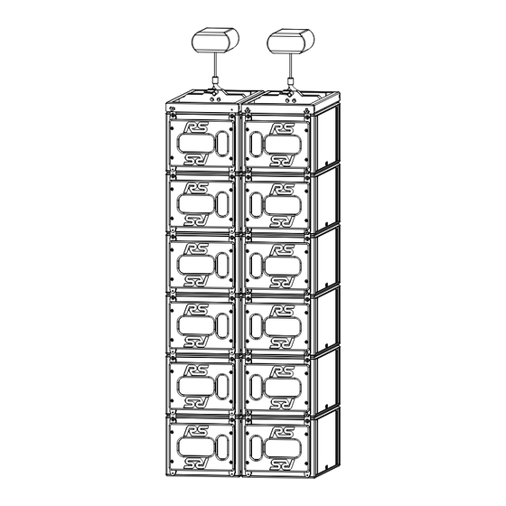
A 12 RS15 cluster flown at 10m/30ft will provide a +/- 3dB pressure level deviation at 100Hz over an audience area 75m/200ft deep while maintaining 15 to 20dB attenuation on stage (see figure below). -
Page 40: Delay Values Implementation
Page 40/58 RAY SUB S IMPLEMENTATION θ θ θ GROUP OF 2 RS15S STEERING GROUP OF 3 RS15S STEERING GROUP OF 4 RS15S STEERING “Steering” delays values for the pairs can easily be computed according to following formula: τ = h*sin(θ)/C (metric) τ... -
Page 41: Coverage Result
RS15’s reference point in Omni Mode is center of the front grid • RS15’s reference point in Directional Mode is center of the face opposite to connector panel. RS15 REFERENCE POINT IN OMNI MODE RS15 REFERENCE POINT IN DIRECTIONAL MODE... -
Page 42: Precautions
8.4.3 Alignment with distance measurement The fastest way to align RS15 arrays to a main system is simply to measure distance difference from listening point to RS15 and main system reference points. being the distance from GEO S12 array to listener position, and r... -
Page 43: Alignment With Phase Measurement
Computer – Laptop or Desktop PC running Windows 2000 or XP with the current version of NEXO GeoSoft2 installed. It is not possible to configure a Geo tangent array properly without using GeoSoft2. Note that, when GeoSoft2 designs are prepared prior to arrival at the venue, it is often necessary to modify or update the design to accommodate special circumstances. -
Page 44: Rs15 System Check List
Make sure that each RS15 driver is producing proper summation in omni mode: The two RS15 individual 15” driver should sum up by 6 dB; Doubling RS15 quantity (2, 4 and so on) should also produce 6 dB gain. •... -
Page 45: Final Pre-Sound Check Check
RS15 S Page 45/58 YSTEM HECK when listening from behind the system, switch the front drivers in and out. You should hear a reduction in the LF range when the both front and rear drivers are on as compared to when the rear drivers only are on;... -
Page 46: Rs15 Technical Specifications
Order RS15-C (finished grey carpeting) or RS15-P (finished in black structured coating) As part of a policy of continual improvement, NEXO reserves the right to change specifications without notice. Response curves and data: anechoic far field above 200 Hz, half-space anechoic below 200 Hz. -
Page 47: Dimensions
RS15 T Page 47/58 ECHNICAL PECIFICATIONS 10.2 Dimensions 42.28" 1074 mm 10.3 Diagrams 10.3.1 Frequency Response and Impedance (dB) Level, Sound pressure Frequency (Hz) OC : Response C urve for 2.83Vrms at NX242 input Amplitude log Frequency (Hz) F: Omni Mode... -
Page 48: Polar Plots
Page 48/58 RS15 T ECHNICAL PECIFICATIONS 10.3.2 Polar plots Omni Mode (2xRS15 front) Directional Mode (2xRS15 side) Directional Mode (2xRS15 alternate) - Page 49 RS15 T Page 49/58 ECHNICAL PECIFICATIONS Directional Mode (2xRS15 face to face – 50cm – 20”) Directional Mode (2xRS15 back to back)
-
Page 50: Rs15 Accessories
Page 50/58 RS15 T ECHNICAL PECIFICATIONS 10.4 RS15 Accessories 10.4.1 RS15-BUMPER Dimensions 43.8" 1113 mm 10.4.2 RS15-FPLATES Dimensions 2.24" 57 mm 10.4.3 RS-15 HANDLES Dimensions... -
Page 51: Rs15-Wheels
RS15 T Page 51/58 ECHNICAL PECIFICATIONS 2.13" 54 mm 10.4.4 RS15-WHEELS Dimensions 3.62" 92 mm... -
Page 52: Rs15-Dolly
Page 52/58 RS15 T ECHNICAL PECIFICATIONS 10.4.5 RS15-DOLLY Dimensions 43.22" 1098 mm 10.4.6 RS15 Push-Pins (BLGEOS) Dimensions 20 mm... -
Page 53: Geo S12 Analogue Tdcontroller
RS15 T Page 53/58 ECHNICAL PECIFICATIONS 10.5 GEO S12 Analogue TDController 10.5.1 Specifications SPECIFICATIONS Output Section +22 /+16/+10 dBm typ. into 600 Ohm load. Back Panel switch on +6/0/-6dB respectively. Input Section Maximum input Level : 22dBu. CMRR 80dB @ 1kHz typ. -
Page 54: Nx242 Digital Tdcontroller With Nx-Tension Card
Individual Mute/Solo buttons and red LED for each channel Amp. Sense & Peak (green & red) LED’s for each channel FLASH EPROM Software updates/upgrades, new system setups, available on www.nexo-sa.com Rear Panel RS232 connector for serial com 2 x RJ45 connectors with NXTension ES4 Card 1 RJ45 + 2 RJ11 with NXTension CAI Card Dimensions &... -
Page 55: Nxamp4X1 & Nxamp4X4 Powered Digital Tdcontrollers
NXAMP4x1: 3U 19” Rack – 457mm (18”) Depth – 16.5kg (33lbs) net NXAMP4x4: 4U 19” Rack – 457mm (18”) Depth – 24.5kg ( 49lbs) net NXAMP USER CONTROLS System Selection Allows control across all NEXO range System Setup Within selected range, allows cabinets to be set for: passive or active;... -
Page 56: Front And Rear Panel View
Page 56/58 RS15 T ECHNICAL PECIFICATIONS 10.7.2 Front and Rear Panel view... -
Page 57: Rs15 Parts & Accessories List
MODEL DRAWING DESCRIPTION RS15-BUMPER Main RS15 Bumper RS15-FPLATES Rigging plate with handles (pair). RS15-HANDLES Handles (pair) RS15-WHEELS 2 Wheels on wood skids (pair) RS15-DOLLY RS15 Dolly (3 RS15 max) BLGEOS Quick Release Pin for Geo S8 / GeoS12 / RS15... -
Page 58: User Notes
Page 58/58 USER NOTES 12 USER NOTES France Nexo S.A. Parc d’Activité de la Dame Jeanne F-60128 PLAILLY Tel: +33 3 44 99 00 70 Fax: +33 3 44 99 00 30 E-mail: info@nexo.fr www.nexo-sa.com...
Need help?
Do you have a question about the RS15 and is the answer not in the manual?
Questions and answers