Table of Contents
Advertisement
BOSCH
INSTALLATION
INSTRUCTION
MANUAL
for
Bosch Electric Built-in
Single & Double Oven Models HBL 53..154../55../56..
_3
i_z)
BEFORE
YOU
BEGIN,
READ
THESE
INSTRUCTIONS
COMPLETELY
AND
CAREFULLY
IMPORTANT:
Save these inst.ru, ctions
for the local electrical
inspector's
use
INSTALLER:
Please
leave this manual
with owner
for future
reference.
|
OWNER:
Please
keep this manual
for future
reference
J
Advertisement
Table of Contents

Related Manuals for Bosch HBL555AUC


Summary of Contents for Bosch HBL555AUC
- Page 1 BOSCH INSTALLATION INSTRUCTION MANUAL Bosch Electric Built-in Single & Double Oven Models HBL 53..154../55../56.. i_z) BEFORE BEGIN, READ THESE INSTRUCTIONS COMPLETELY CAREFULLY IMPORTANT: Save these inst.ru, ctions for the local electrical inspector's INSTALLER: Please leave this manual with owner for future reference.
-
Page 2: Table Of Contents
Table of Contents INTRODUCTION ..........................Tools You Will Need ........................Power Requirements ........................Choosing Oven Location ......................Steps for Installation ............_............TECHNICAL DATA ......................... Single oven ........................... Double oven ..........................UNDERCOUNTER INSTALLATION ..................SINGLE OVEN ..........................WALL INSTALLATION ........ -
Page 3: Introduction
INTRODUCTION a 208 volt circuit must be used, wiring inside the oven must be modified. See Connection to a 208 Volt Circuit, in this manual. A circuit breaker Please read these instructions COMPLETELY time-delay fuse sized not to exceed the circuit rat- CAREFULLY. -
Page 4: Technical Data
TECHNICAL DATA SINGLE OVEN For cutout dimensions see following sections rifled: Preparing Location Electrical Ratings and Maximum Connected Load Convection Single Oven Models Oven Watts Volts Hertz Amperes @240V/208V @240V/208V HBL 532A UC 240/208 13.5/13.6 3,250/2,820 HBL 535A UC 240/208 13.5/13.6 3,250/2,820 HBL 536A UC... -
Page 5: Undercounter Installation
UNDERCOUNTER INSTALLATION, SINGLE Oven eleclflcaJsupply:. Locate Ju_tion b_ in adjacent cabinet or below bottom support surface. < 28" opening width Bottomsupport sul/eee must be solid, level and able to suppod at leest of 150 Ibs. 1/4" rain. dlstance between oven door •... -
Page 6: Wall Installation
WALL INSTALLATION, SINGLE OVEN ::_: iSiK_to _the Screws i the mounti ho4e_s In ktn_e frame door to see frame and mounting Do not overtighten screws. Note: Do not slide oven across floor. Dam- 6. Be careful when placing oven. DO NOT pinch the conduit between age to floor covering or floor could re-... -
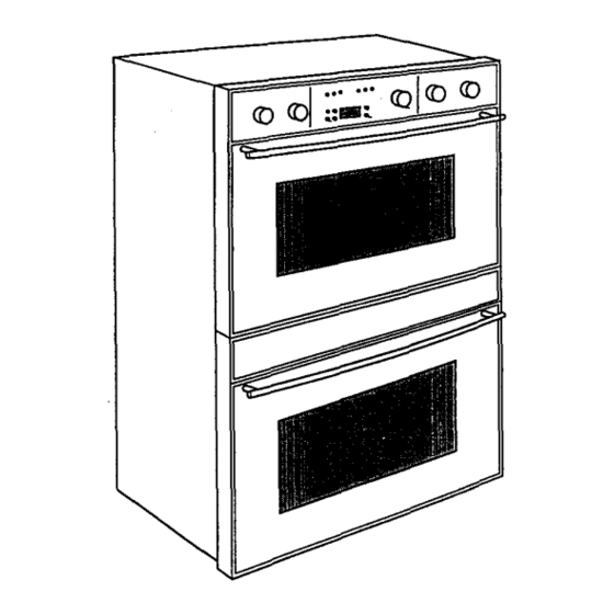
Page 7: Double Oven
WALL INSTALLATION, DOUBLE OVEN Secure oven to cabinet using b_e screws prided. Screws should be inserted through the mounting holes in the positions indicated in the frame (open door to see frame and mounting holes). Do not overtighten screws. Note: Do not slide oven across floor. -
Page 8: Electrical Supply
ELECTRICAL SUPPLY WIRING REQUIREMENTS When making the wire connections, use the entire length of the conduit provided (3 feet). The con- Before installing the oven have a qualified electri- duit must not be cut. cian verify that your home is provided with ade- Before making connections make sure the power... -
Page 9: Connecting To 208 Volt Circuit
CONNECTING TO 208 V CIRCUIT To connect to 208 volt circuit: Remove the access panel(s) located on the The ovens are pre-wired for connection to 240 back of the oven(s). volt, 60 Hertz supply. If connecting to a 208 volt, Loosen the first and second screws in the ter- 60 Hz. -
Page 10: Electrical Connections
ELECTRICAL CONNECTIONS 3-WIRE BRANCH CIRCUIT Refer to Figure A, where local codes allow connection of GROUND wire from the cook-top This appliances is manufactured with a green GROUND wire connected to the oven chassis. to the branch circuit NEUTRAL wire (grey white colored wire):... -
Page 11: Final Checklist
FINAL CHECK LIST volt the voltage reading between the black and red wires should be 190 to 208 volts. time pressing the Set To prevent improper connections leading to dam- Clock button and pressing the plus (+) or mi- age of electrical components and so voiding nus (-) button,...
Need help?
Do you have a question about the HBL555AUC and is the answer not in the manual?
Questions and answers