Advertisement
Quick Links
Download this manual
See also:
Instructions for Using
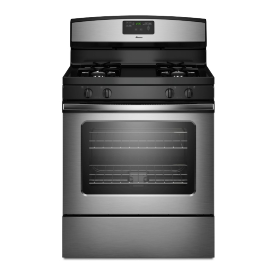
INSTALLATION INSTRUCTIONS
30" (76.2 CM) FREESTANDING GAS RANGES
Tableof Contents
RANGE SAFETY ......................................................................................
1
.........................................................
3
Tools and Parts ....................................................................................
3
Location Requirements ........................................................................
3
Electrical Requirements .......................................................................
5
...................................................................
5
INSTALLATION
INSTRUCTIONS
...........................................................
7
Unpack Range ......................................................................................
7
Install Anti-Tip Bracket .........................................................................
7
Make Gas Connection ..........................................................................
8
Verify Anti-Tip Bracket Is Installed and Engaged ................................
9
Level Range ........................................................................................
10
Electronic Ignition System ..................................................................
10
Warming Drawer or Premium Storage Drawer ..................................
12
Storage Drawer ..................................................................................
12
Oven Door ..........................................................................................
13
Complete Installation ..........................................................................
13
GAS CONVERSIONS
............................................................................
14
LP Gas Conversion ............................................................................
14
Natural Gas Conversion .....................................................................
17
RANGESAFETY
Your safety and the safety of others are very important.
We have provided many important safety messages in this manual and on your appliance. Always read and obey all safety
messages.
This is the safety alert symbol.
This symbol alerts you to potential hazards that can kill or hurt you and others.
All safety messages will follow the safety alert symbol and either the word "DANGER" or "WARNING."
These words mean:
You can be killed or seriously injured if you don't immediately
follow
instructions.
You can be killed or seriously injured if you don't follow
instructions.
All safety messages will tell you what the potential hazard is, tell you how to reduce the chance of injury, and tell you what can
happen if the instructions are not followed.
iMPORTANT:
Save for local inspector's use.
installer: Leave installation instructions with the homeowner.
Homeowner:
Keep installation instructions for future reference.
W10526974A
Advertisement


Need help?
Do you have a question about the AGR5630BDW0 and is the answer not in the manual?
Questions and answers