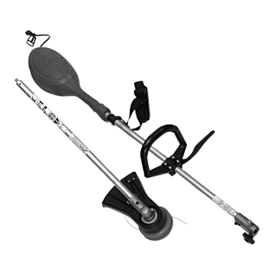
Mantis “E” System Owner's Manual And Safety Instructions
Line trimmer
Hide thumbs
Also See for “E” System:
- Owner's manual and safety instructions (14 pages) ,
- Owner's manual and safety instructions (13 pages) ,
- Owner's manual and safety instructions (12 pages)
Subscribe to Our Youtube Channel
Summary of Contents for Mantis “E” System
- Page 1 Line Trimmer “E” System Owners Manual and Safety Instructions © 2006 Mantis, Div. of Schiller-Pfeiffer Inc. All Rights Reserved.
-
Page 2: Table Of Contents
Table of Contents Important Information Assembly Instructions ....5 Introduction ......1 Operation . -
Page 3: Safety And Warnings
Safety and Warnings A. Safety Decals READ AND Please pay particular attention to the warning and information UNDERSTAND decals found on various parts of this Line Trimmer Attachment OPERATOR’S MANUAL unit. They are an important part of the safety system. These BEFORE USING! KEEP decals must be replaced in time due to abrasion, etc. -
Page 4: General Safety Rules
General Safety Rules Never lean over the rotating cutting head. Rocks or other debris could be thrown into eyes and face and cause serious personal injury. 10. Do not abuse the cord. WARNING Never carry the tool by the cord or yank it to disconnect it WHEN USING ELECTRIC TOOLS, BASIC SAFETY from the socket. - Page 5 “E” system. Have repairs made by a qualified repairman. switches replaced by an authorized service facility. Do not See that only original “Mantis” parts are used. use the tool if the switch does not turn it on and off. 33. Maintain a firm footing and good balance, do not Don’t operate the machine with a damaged or excessively...
-
Page 6: Assembly Instructions
Assembling the Line Trimmer 1. Locate and open sealed bag with 3 screws, 3 split washers, 4. Place gear case cover #4 onto the gear shaft. clamp plate #2 and L-pin. (Picture 1) (Pictures 4 and 5) 2. Remove plastic tube and gear case cover #4 from the 5. -
Page 7: Operation
Attaching the Line Trimmer Trimming Techniques to the Power Head 1. With both hands on the handles, push lockout trigger No tools are required to attach the Line Trimmer to the power button with your thumb first, and then squeeze trigger. head assembly. - Page 8 THE POWER SOURCE. Picture 14 Picture 15 Replacement spools can be ordered through your Mantis dealer. 1. For safety reasons, do not use metal reinforced line. 2. For replacement use 0.095" dia line. The spool is capable to hold approximately 20' long line.
-
Page 9: Maintenance
Maintenance Area Maintenance procedure Frequency Spline male/female connection of the inner drive shaft Pull Loosen Remove Inspect/Lubricate 1. Remove center screw, and loosen up other two as shown on the diagram (left). 20-25 Hrs 2. Pull the shaft from the gear housing. 3. - Page 10 Line Trimmer “E” System Exploded View 40 40 38 38 39 39 37 37 36 36 14 14 13 13 16 16 12 12 15 15 28 28 18 18 17 17 29 29 35 35 41 41 42 42 30 30 33 33 32 32...
- Page 11 Line Trimmer “E” System Parts List KEY # DESCRIPTION PART # KEY # DESCRIPTION PART # GEAR CASE-ASS’Y 331186 SPRING 331204 GEAR CASE 331187 PLATE 331205 BEARING 609 331146 SPOOL HOLDER 331206 GEAR 331188 CENTER INSERT 331207 MAIN GEAR HOUSING SHAFT 331189 GUARD ASS'Y BEARING 6201 331190...
- Page 12 This warranty covers all portions of the Mantis Line Trimmer Attachment. MANTIS will repair or replace, at its option, any part or parts of the product proven to be defective in material or workmanship under normal usage during the warranty period. Warranty repairs and replacements will be made without charge for parts or labor.


Need help?
Do you have a question about the “E” System and is the answer not in the manual?
Questions and answers