Jenn-Air JED8130 Installation Manual
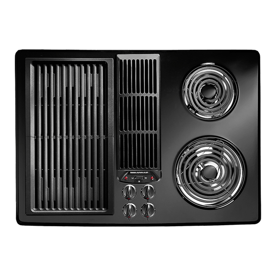
Electric convertible cooktop
Hide thumbs
Also See for JED8130:
- User manual (40 pages) ,
- Installation manual (9 pages) ,
- Use & care manual (24 pages)
Advertisement
Quick Links
Electric Convertible
Cooktop I
: JENN-AIR
1
Models JED8130, JED8230 & JED8345 _ WEST
FOURTH
STREET, NORTH" NEWTON,
IA 50208
DIMENSIONS SHOWN IN BOTH INCHES AND CENTIMETERS
*Blower may be rotated for horizontalor verticaldirectionby looseningnuts aroundblower inlet. Accessible insideventilation
chamber.
TIE DOWN BOLT
ON EACH
:'ASE
CONTAINER
• NOTICE TO INSTALLER: Leave these instructions
with the appliance.
• NOTICE TO CONSUMER: Retain these instructions
for future reference.
23.8t cm
MODEL SERIES: JED8345 TRIPLE BAY
ql
Typ. for Container Supplied,
6 1/4" (1,5,88 cm) is required for removal.
13
t5/]6"
35.
I
¢m
1
CONTAINER
!
2
718 ° _
'
7,3
crn
"_= "=,_
2 7/8"
68.0
cm
7.3
cm
34.9
o"a
30.0
cm
ONLY MODELS WITH GRILLING FEATURE HA VE BEEN ILLUSTRATED
INSTRUCTIONS TO INSTALLER,
• Dimension "B" - Provide 2" min. (5.08 cm) cabinet clearance to motor for cooling purpose,
• Installer - Where possible, 6" (15.24 cm) is recommended for motor/blower service.
• Side Clearance - Grill models installed near a side wall must allow a minimum clearance of 6" (15,24 cm) for
maximum performance.
° Electrical Hook UP - The unit should be properly circuit protected and wired according to local electrical codes. See
electrical wiring information on back, Unit power requirements are located on the data plate.
• ** Access must be provided to remove and empty grease container(s).
8101 P421 ..60
(10-01-oo)
A
INCHES
CM
Double Bay
29 + 1/16"
73.66
TriPle Bay
43 1/4 + 1/i6
109.86 + 116
MODEL SERIES: JED8130 & JED8230 DOUBLE BAY
_EASE
Advertisement

Related Manuals for Jenn-Air JED8130


Summary of Contents for Jenn-Air JED8130
- Page 1 Cooktop I : JENN-AIR Electric Convertible Models JED8130, JED8230 & JED8345 _ WEST FOURTH IA 50208 STREET, NORTH" NEWTON, DIMENSIONS SHOWN IN BOTH INCHES AND CENTIMETERS *Blower may be rotated for horizontalor verticaldirectionby looseningnuts aroundblower inlet. Accessible insideventilation chamber. • NOTICE TO INSTALLER: Leave these instructions with the appliance.
- Page 2 Installing Cabinetry Over Your Jenn-Air Grill Electrical Wiring Information A* = 30" (76.2 cm) minimum clearance between the top of The neutralof this unitis groundedto the frame through the the cookingplatformand the bottomof an unprotected green grounding wire. If local conditions do not permit wood or metal cabinet.
- Page 3 240 EdwardsStreet, SE Cleve!an&Tennessee 37311 Tel: 423-472-3333 Fax:423-478-6710 4. FREE-STANDING CUTOUT - 30 I/8"(76.52 cm) minimum clearance isrequired. - Carefully mark thecounter top, recheck yourdimensions a ndmake thecutout. - NOTE: Range sidepanels may be desirable if thecutout i stoolarge orcabinets areon oneside of therangeonly.
- Page 4 2.40EdwardsStreet,SE Cevetand.Tennessee 3721l Te, l: 422-472-3333 Fax:423-478-5710 7. SLIDE-IN CUTOUT - Check your marked-up dimensions carefully. The reardimensionsshown intheillustration must be maintained. - NOTE: Where thisisnot done, it willbe necessaryto relieve a portion of theundersideof the countertopand/or supportmembers toclearthe range mar panel. - Cuttingtolerance is 4- 1/16"...
- Page 5 C_.stomer SeP:ic_ Z40 EawardsSLreet,SE C1eve!and, Tennessee 3 7311 Tei: _22-472-3333 Fax:_23-478-6710 I0. FLOOR VENT CUTOUT (JOISTS AS SHOWN) - Check the direction of the floor joists (see illustration), tf the joists' direction is as shown, locate the cutout on the '7" as illustrated. The cutout must miss the floarjoists! - Cutout may be moved from side to side on line to clear floor joist.
-
Page 6: Connect Electrical
2J-g Eawa_ds StreeL SE C;eveiand, T ennessee 37311 Tel:423-477.-;333 Fax:'_23-J-78-67! 0 INSTALL BLOWER (PRIOR TO INSTALLING RANGE) - Refer to your vent plan. It may be desirable to attach part of the ducting to the blower before it is installed. - Position the blower (see illustration) and attach it to the floor with at least two (2) screws. - Page 7 Custcmef Serwc8 240EdwardsStreet SE Ceveiand.Ten_esse_ 37211 T_: 473-472-2223 Fax: _ 23-478-87t0 16. CONNECT ELECTRICAL (FOUR CONDUCTOR WIRE) - CAUTION: Make sure power to cable is OFF. - Remove the range electrical service cover located on the back, lower left-hand corner. Remove the strap,, s crew and bend the up as shown.
-
Page 8: Anti-Tip Bracket Installation
Cus[ome r _ePdc_ 2_0EdwardsStreet, SE Ceveian_.Tennessee 373I I Te!: a22-'72-3333 ANTI-TIP BRACKET INSTALLATION - With the unit installed in the final location, establish left side and back of the unit. - Locate left bracket 5/8" (1.58 cm) in from the left of the unit. - Locate the right bracket 27 718"... - Page 9 24(3 EdwardsStree[.SE C[eveiane. T ennessee 3731'[ Tel:423-472_-3333 Fax:_23-47_,.,_710 22. INSTALL FLEX DUCT - Attach the flex duct to the blower and range (See illustration). Using a screwdriver, securely tighten duct clamp at each connection, 23. CHECK OPERATION - Unpack and install grill element in one side and cooking cartridge in other side, - Be sure to remove all packaging materials from unit prior to applying power.
Need help?
Do you have a question about the JED8130 and is the answer not in the manual?
Questions and answers