Table of Contents
Advertisement
Quick Links
Advertisement
Table of Contents

Subscribe to Our Youtube Channel
Related Manuals for Hafler TRM6.1


Summary of Contents for Hafler TRM6.1
-
Page 2: Declaration Of Conformity
Importer’s Name: ________________________________________________________ Importer’s Address: ________________________________________________________ Type of Equipment: 2-channel Audio Power Amplifier/Speaker Model No.: TRM6.1 Serial Number: Year of Manufacture: I, the undersigned, hereby declare that the equipment specified above conforms to the above Directive(s) and Standard(s) Place: Hafler... -
Page 3: Specifications
ERFORMANCE TRM6.1 Free Field Frequency Response 55Hz–21kHz, ±2dB ≥119dB (per pair w/music @ 1m) Peak Acoustic Output Total Harmonic Distortion (THD) <0.5%, 150Hz–21kHz (90dB @ 1m on axis) High Frequency Driver 1" (25mm) Vifa Soft Dome Low Frequency Driver 6.5" (165mm) Polypropylene Cone/... - Page 4 TO PREVENT FIRE OR SHOCK HAZARD DO NOT EXPOSE THIS EQUIPMENT TO RAIN OR MOISTURE. READ INSTRUCTIONS All the safety and operating instructions of your Hafler equipment should be read before power is applied to the equipment. RETAIN OWNER'S MANUAL These safety and operating instructions should be retained for future reference.
- Page 5 ADVERTENCIA – INFORMACION DE SEGURIDAD IMPORTANTE LEA LAS INSTRUCCIONES Todas las instrucciones de seguidad y operación de su equipo Hafler, deben ser leídas antes de que el equipo sea conectado dléctricamente. CONSERVE EL MANUAL DEL PROPIETARIO Estas instrucciones de seguridad y operación, deben ser conser- vadas para futuras referencias.
- Page 6 à éviter toute pénetration dans l'enceinte du matériel. 14. DÉGÂT NÉCESSITANT UNE RÉVISION Le matériel Hafler devrait être révisé par des personnes qual- ifées de service après-vente, lorsque: A. Les fiches ou la prise de courant ont été endommagé, ou: B.
- Page 7 ACHTUNG – WICHTIGE SICHERHEITS – INFORMATIONEN INSTRUKTIONEN LESEN Alle Sicherheits- und Operationshinweise Ihres Hafler Equipments sollten vor der Inbetriebnahme gelesen werden. BETRIEBSANLEITUNG AUFBEWAHREN Bewahren Sie die Bedienungsanleitung sorgfältig auf, damit Sie in dieser auch in Zukunft nachschlagen können. WARNUNGEN BEACHTEN Alle Warnungen des Gerätes und der Bedienungsanleitung sind...
- Page 8 Si deve prestar attenzione che oggetti e liquidi, come fluidi deter- genti e bibite, non vengano versati all'interno dell'apparato. 14. RIPARAZIONI Gli apparati Hafler devono essere riparati da personale qualifica- to quando: A. Il cavo di alimentazione o la spina sono danneggiati B.
-
Page 9: Table Of Contents
ABLE OF ONTENTS PERFORMANCE SPECIFICATIONS Frequency Response Graph Energy Time Curve Graph Horizontal Polar Response Graph Dimensions SAFETY PRECAUTIONS ...ii INTRODUCTION ...1 TECHNICAL DESIGN FEATURES ...1 FRONT & REAR PANEL VIEWS ...4 INSTALLATION Location ...5 Determining Acoustic Center ...6 Input Switch ...6 XLR Wiring Configurations ... -
Page 10: Introduction
NTRODUCTION Thank you and congratulations on your purchase of the HAFLER TRM6.1 reference monitor, the world's finest brand in professional audio equipment. The TRM6.1 (Trans•ana Reference Monitor) is a bi-amplified, two-way near field monitor offering unmatched quality and performance in a truly professional grade product. The TRM6.1 is great for Professional Studios, Digital Work Stations, Broadcast Booths, and Home Project Studios. - Page 11 MOSFET Devices HAFLER is one of the few manufacturers in the sound community to utilize MOSFET devices in both the power supply and output stages. MOSFET (Metal Oxide Semiconductor Field Effect Transistor) devices offer several important inherent advantages over the 30-year-old technology of bi-polar design. These advantages include: ther- mal stability, fast switching speed, ultra low output impedance and wide bandwidth linearity.
- Page 12 Tweete Wave Guide The wave guide is a proprietary axis-symmetrical form of horn mounted to the tweeter to increase efficiency. The wave guide improves the transition of sound waves (from planar to spherical) smoothly from the throat of the wave guide to the mouth.
-
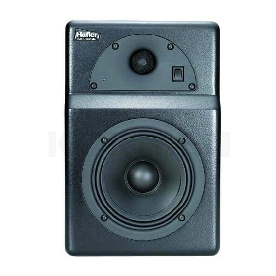
Page 13: Front Panel View
Front Panel View Tweeter Wave Guide Status LED Woofer Rubber Pad Rear Panel View Power Switch Balanced Input Unbalanced Input Input Switch Sensitivity Bass Roll Off Bass Shelving Treble Shelving Heatsink AC Line Input AC Line Fuse... -
Page 14: Installation
NSTALLATION LOCATION The location of your reference monitors in addition to the acoustics of the listening room will influence the system frequency response. In the near field environment, our ears are more sensitive to direct sound rather than the reverberation of sound. Below are some recommendations for the initial set-up which may help you optimize performance in complex acoustic envi- ronments. -
Page 15: Determining Acoustic Center
Systems, 1501 West 17th Street, Tempe, Arizona 85281-6255, TEL (602) 829-8000 FAX (602) 756-9000. OmniMount Systems is not affiliated with Hafler or Rockford Corporation. Connect (–) and GND (shield) terminals at both ends of cable to prevent unstable amplifier operation... -
Page 16: Schematic Diagram
CHEMATIC IAGRAM NOTES: Unless specified otherwise 1. All resistors in ohms. 2. All capacitors in microfarads. 3. Channel 1 only shown. – 7 –... - Page 17 Qualified Service Personnel Only –8–...
- Page 18 CHEMATIC IAGRAM NOTES: Unless specified otherwise 1. All resistors in ohms. 2. All capacitors in microfarads. 3. Channel 1 only shown. – 9 –...
- Page 19 Qualified Service Personnel Only –10–...
- Page 20 NOTES: Unless specified otherwise 1. All resistors in ohms. Qualified Service Personnel Only 2. All capacitors in microfarads. 3. Channel 1 only shown.
-
Page 21: Pc Board Layout
Qualified Service Personnel Only... -
Page 22: Operation
PERATION NOTE: When using the INPUT SENSITIVITY, select only one switch configuration at a time. Engaging multiple switch configurations (i.e., moving two or more switches ON) may cause undesirable operation and is NOT RECOMMENDED. INPUT SENSITIVITY The Input Sensitivity adjustment is used to match the monitor with signal levels from a variety of mixing consoles. The Input Sensitivity uses DIP switches to match input levels over a 15dB range and are marked +1dB, –2dB, –5dB, –8dB, and –11dB. -
Page 23: Bass Shelving
AC LINE The TRM6.1 operates from a 115 VAC/60Hz power line. The TRM6.1CE operates from a 230 VAC 50/60Hz power line. Connection is made by a 16 gauge, IEC Type 320, grounded line cord. For safety considerations only a properly ground- ed (earthed) receptacle should be used. -
Page 24: Power Switch
POWER SWITCH The POWER switch is located on the front panel. The LED will illuminate GREEN, indicating the respective amplifiers are on. It is possible to leave the power switch in the ON position and switch the monitor remotely through a power distribution block or switched outlet. -
Page 25: Parts List
ARTS DESIGNATOR VALUE ALL RESISTORS IN OHMS RES 1.0K OHM 1/10W 1% RES 47K OHM 1/10W 5% R102 RES 6.8K OHM 1/4W 5% R103 RES 6.8K OHM 1/4W 5% R104 POT 5K 10% PIHER R105 RES 1.0K OHM 1/10W 1% R106 35.7K OHM 1/10 WATT 1% R107... - Page 26 RES 280 OHM 1/10W 1% RES 10 OHM 1/10W 5% RES 100 OHM 1/4W 5% RES 2.21K OHM 1/10W 1% RES 2.21K OHM 1/10W 1% RES 100K OHM 1/10W 5% 619K OHM 1/10W 1% RES 1M OHM 1/10W 5% RES 1M OHM 1/10W 5% POT 2K TRIM RES 6.49K OHM 1/10W 1% RES 6.49K OHM 1/10W 1%...
- Page 27 Regulator LM337 XSTR MMBT5088L NPN XSTR MMBT5088L NPN XSTR MMBT3906LT1 PNP XSTR MMBT3906LT1 PNP XSTR MMBT3906LT1 PNP XSTR MPS6521 XSTR MMBT3906LT1 PNP XSTR MMBT3906LT1 PNP XSTR MMBTA06L XSTR MMBT3906LT1 PNP XSTR MMBT3906LT1 PNP XSTR MMBT3904LT1 NPN OPAMP TL072CD U112 OPAMP TL072CD OPAMP TL072CD OPAMP TL072CD OPAMP TL072CD...
-
Page 28: Functional Block Diagram
TRM6.1 F UNCTIONAL LOCK IAGRAM – 19 –... -
Page 29: Service Reference
ERVICE EFERENCE CIRCUIT OPERATION Qualified Service Personnel Only trans•ana Implementation The transistor Q24 is configured to operate as a switch that controls the constant current source Q21 of the differ- ential amplifier Q27 and Q28. Switch Q24 is under the control of the thermal and turn-on circuits, and provides a Soft Start turn-on ramp according to the charging time of C70 through R13 and R156. -
Page 30: Input Circuit
Input Circuit The input signal is connected to the amplifier through the balanced XLR connector J1, or the unbalanced RCA connector J2. Balanced/unbal- anced switch DS1 will ground the inverting input buffer, allowing operation with an unbalanced signal on either connector. Input buffers U1A and U1B provide a stable input impedance, dominat- ed by R10 and R4. -
Page 31: Woofer Crossover
Woofer Crossover The input signal at U4A pin 1 connects to the 3200Hz 2nd order low-pass filter at U112B. Approximately 2dB of additional gain can be added to this stage by adjusting R136 against the divider resistor, R137. The next stage is a 30Hz–60Hz switchable sub-sonic high-pass filter. -
Page 32: Clipping Indicator
Qualified Service Personnel Only Clipping Indicator The CLIP indicators are driven by the comparator U5A and U5D. The voltage divider R56, R57, and R51, R61 establishes the reference voltage for the Clipping detector at pin 7 of U5A and pin 9 of U5D. Excessive drive sig- nal at pin 6 or pin 8 will trigger its comparator low and light the CLIP/THERMAL indicator red. -
Page 33: Tweeter Replacement
TWEETER REPLACEMENT 1. Remove (4) screws from wave guide using a 3/32" Allen Wrench 2. Remove wave guide assembly from enclosure 3. Disconnect the LED harness (FIG. 1) 4. Disconnect the (2) speaker wires from the tweeter (FIG. 2) 5. Disconnect the (2) power switch wires (FIG. 3) 6. -
Page 34: Amplifier Replacement
FIG. 7 PCB Mounted Speaker Wires TRANSFORMER REPLACEMENT The TRM6.1 is available both 120V and 230V versions. If it is necessary to perform service on the amplifier, be sure to check connections to the transformer before re-applying power and/or re- assembling the unit. -
Page 35: Warranty
Some states do not allow limitations on the length of an implied warranty, so this limitation may not apply. No person is authorized to assume for Hafler any other liability in con- nection with the sale of the product. - Page 36 HAFLER A DIVISION OF ROCKFORD CORPORATION 546 SOUTH ROCKFORD DRIVE TEMPE, ARIZONA 85281 U.S.A. 1.866.GOHAFLER 480.967.3565 WWW.HAFLER.COM MADE IN THE USA This product is designed, developed and assembled in the USA by a dedicated group of American workers. The majority of the components used in the con- struction of this product are produced by American companies.
Need help?
Do you have a question about the TRM6.1 and is the answer not in the manual?
Questions and answers