Table of Contents
Advertisement
Quick Links
Advertisement
Table of Contents

Related Manuals for SOYO SY-K7VTA-B


Summary of Contents for SOYO SY-K7VTA-B
- Page 1 SY-K7VTA-B Motherboard **************************************************** ® Athlon/Duron Processor supported VIA KT133 AGP/PCI Motherboard 200 MHz Front Side Bus supported ATX Form Factor **************************************************** User's Manual...
- Page 2 It is the policy of Soyo Computer Inc. to respect the valid patent rights of third parties and not to infringe upon or to cause others to infringe upon such rights.
-
Page 3: Table Of Contents
Table of Contents SY-K7VTA-B Table of Contents CHAPTER 1 MOTHERBOARD DESCRIPTION ......1 INTRODUCTION ............1 KEY FEATURES ............1 ELECTROSTATIC DISCHARGE PRECAUTIONS ..5 SY-K7VTA-B MOTHERBOARD LAYOUT ....6 SY-K7VTA-B MOTHERBOARD COMPONENTS..7 MICROPROCESSOR............9 MEMORY..............10 CHIPSET ..............12 I/O INTERFACE CONTROLLER .........15 1-10 HARDWARE MONITOR..........17 1-11 WAKE ON LAN TECHNOLOGY.........18... - Page 4 Table of Contents SY-K7VTA-B STANDARD CMOS SETUP ..........54 ADVANCED BIOS FEATURES........57 ADVANCED CHIPSET FEATURES......61 INTEGRATED PERIPHERALS ........66 POWER MANAGEMENT SETUP ........71 PNP/PCI CONFIGURATION SETUP......75 PC HEALTH STATUS............78 LOAD FAIL-SAFE DEFAULTS........80 3-10 LOAD OPTIMIZED DEFAULTS........81 3-11 SUPERVISOR PASSWORD...........82 3-12 USER PASSWORD............83 3-13 IDE HDD AUTO DETECTION ........84...
-
Page 5: Chapter 1 Motherboard Description
SY-K7VTA-B as well. Ø CPU SETTINGS The SY-K7VTA-B provides the user with a very complete and convenient CPU setting environment. The CPU settings are all adjusted through the special SOYO COMBO page in the BIOS, therefore rendering the use of jumpers obsolete. - Page 6 Motherboard Description SY-K7VTA-B CPU Multiplier Ø EXPANDABILITY The SY-K7VTA-B provides all the standard expansion slots, and many more additional expansion features: Expansion slots 1 x 32-bit bus master AGP slot 5 x 32-bit bus master PCI slots 1 x 16-bit ISA slots...
- Page 7 FLOPPY DRIVE & HDD, LS120, SCSI, ZIP. Power on by modem or alarm If the SY-K7VTA-B system is in suspend mode, it can be switched back on through the modem or RTC alarm function. This opens a lot of possibilities, such as remote access that switches the system on only after the modem receives a call.
-
Page 8: Voice Doctor
Motherboard Description SY-K7VTA-B Ø USER FRIENDLY SOYO Combo Setup Jumperless design You can set up the following options trough the BIOS setting CPU FSB frequency CPU multiplier by H/W switch CPU Vcore voltage PCI clock AGP Clock SDRAM Clock Ø... -
Page 9: Electrostatic Discharge Precautions
Motherboard Description SY-K7VTA-B Ø HANDLING THE MOTHERBOARD To avoid damage to your Motherboard, follow these simple rules while unpacking: Ø Before handling the Motherboard, ground yourself by grasping an unpainted portion of the system's metal chassis. Ø Remove the Motherboard from its anti-static packaging. Hold the Motherboard by the edges and avoid touching its components. -
Page 10: Sy-K7Vta-B Motherboard Layout
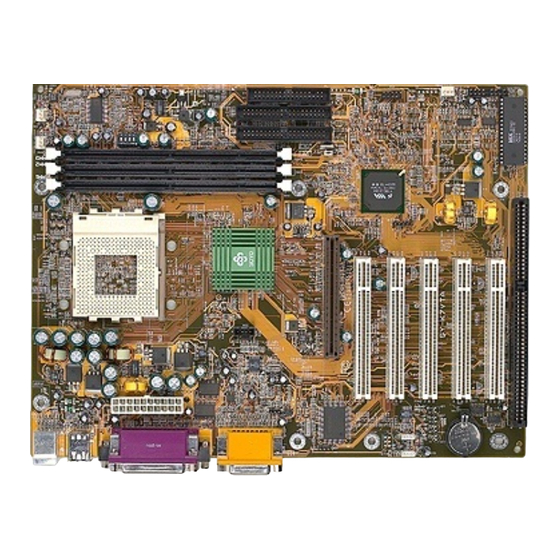
Motherboard Description SY-K7VTA-B 1-4 SY-K7VTA-B MOTHERBOARD LAYOUT PS/2 KB PS/2 Mouse Connector Connector USB 1_2 COM1 COM2 ATX Power GAME SDRAM LINE-OUT ® LINE-IN VT8363 MIC-IN SDRAM CDIN1 AGP Slot IDE 1 IDE 2 Sigmatel STAC9721 PCI Slot #1 ®... -
Page 11: Sy-K7Vta-B Motherboard Components
Motherboard Description SY-K7VTA-B 1-5 SY-K7VTA-B MOTHERBOARD COMPONENTS SDRAM ® SDRAM ®... - Page 12 Motherboard Description SY-K7VTA-B ATX Power Supply Connector Socket 462 Connector Ratio adjustment setting Jumper Via VT8363 North Bridge chip DIMM Banks CPU Cooling Fan Connector Ratio adjustment setting switch Ratio adjustment setting Jumper Bus Mastering E-IDE/ATAPI Ports Floppy Disk Drive (FDD) Port...
-
Page 13: Microprocessor
Motherboard Description SY-K7VTA-B 1-6 MICROPROCESSOR The motherboard supports a single Socket 462 processor. The processor’s VID pins automatically program the voltage regulator on the motherboard to the required processor voltage. In addition, the front side bus speed (200 MHz ) is automatically selected. The motherboard supports all current Socket 462 processor speeds, voltages, and bus frequencies. -
Page 14: Memory
Motherboard Description SY-K7VTA-B 1-7 MEMORY 1-7.1 Main Memory The motherboard has three DIMM sockets. SDRAM can be installed in one, two, or three sockets. Using the serial presence detect (SPD) data structure, programmed into an E²PROM on the DIMM, the BIOS can determine the SDRAM’s size and speed. - Page 15 Motherboard Description SY-K7VTA-B Seamless DRAM command scheduling for maximum DRAM bus utilization (e.g., precharge other banks while accessing the current bank) Four cache lines (32quadwords) of CPU to DRAM write buffers Four cache lines 32 quadwords of CPU to DRAM read prefetch...
-
Page 16: Chipset
Motherboard Description SY-K7VTA-B 1-8 CHIPSET Ø VT8363 The KT133 chip set consists of the VT8363 system controller (552 pin BGA) and the VT82C686B PCI to ISA bridge (352 pin BGA). The system controller provides superior performance between the CPU, DRAM, AGP bus, and PCI bus with pipelined, burst, and concurrent operation. - Page 17 Motherboard Description SY-K7VTA-B buffers and sixteen levels (doublewords) of prefetch buffers are included for concurrent PCI bus and DRAM/cache accesses. The chip also supports enhanced PCI bus commands such as Memory-Read-Line, Memory-Read-Multiple and Memory-Write-Invalid commands to minimize snoop overhead. In addition, advanced features are supported...
- Page 18 Motherboard Description SY-K7VTA-B software can run transparently in non-USB-aware operating system environment. 3) Keyboard controller with PS2 mouse support. 4) Real Time Clock with 256 byte extended CMOS. In addition to the standard ISA RTC functionality, the integrated RTC also includes the date alarm, century field, and other enhancements for compatibility with the ACPI standard.
-
Page 19: I/O Interface Controller
Motherboard Description SY-K7VTA-B level triggered interrupts channel by channel. The integrated DMA controller supports type F DMA in addition to standard ISA DMA modes. Compliant with the PCI2.2 specification, the VT83C686A supports delayed transactions and remote power management so that slower ISA peripherals do not block the traffic of the PCI bus. -
Page 20: Serial Ports
Motherboard Description SY-K7VTA-B Data rates up to 1Mbps Perpendicular recording driver support Two FDDs with drive swap support Plug and play with 48 base IO address, 12 IRQ and 4 DMA options The Setup program provides configuration option for the I/O controller. -
Page 21: Hardware Monitor
Motherboard Description SY-K7VTA-B 1-9.4 PS/2 Keyboard and Mouse Interface PS/2 keyboard and mouse connectors are located on the back panel of the motherboard. The +5 V lines to keyboard and mouse connectors are protected with a fuse that prevents motherboard components from being damaged when an over-current condition occurs. -
Page 22: Wake On Lan Technology
Motherboard Description SY-K7VTA-B subsystem include: Ø An integrated ambient temperature sensor Ø Fan speed sensors, which monitor the fan 1 and fan 2 connector. Ø Power supply voltage monitoring to detect levels above or below acceptable values When suggested ratings for temperature, fan speed, or voltage are exceeded, an interrupt is activated. -
Page 23: Chapter 2 Hardware Installation
SY-K7VTA-B Chapter 2 HARDWARE INSTALLATION Congratulations on your purchase of SY-K7VTA-B Motherboard. You are about to install and connect your new Motherboard. Note: Do not unpack the Motherboard from its protective anti- static packaging until you have made the following preparations. -
Page 24: Unpacking The Motherboard
BIOS Setup Utility SY-K7VTA-B UNPACKING THE MOTHERBOARD When unpacking the Motherboard, check for the following items: The SY-K7VTA-B KT133 AGP/PCI Motherboard The Quick Start Guide The Installation CD-ROM SOYO Bonus Pack CD-ROM One IDE Device ATA 66 Flat Cable One Floppy Disk Drive Flat Cable Warning: Do not unpack the Motherboard from its anti-static packaging until you are ready to install it. -
Page 25: Installation Guide
BIOS Setup Utility SY-K7VTA-B 2-3 INSTALLATION GUIDE We will now begin the installation of the Motherboard. Please follow the step-by-step procedure designed to lead you to a complete and correct installation. Warning: Turn off the power to the Motherboard, system chassis, and peripheral devices before performing any work on the Motherboard or system. -
Page 26: 2-3.1 Cpu Installation
BIOS Setup Utility SY-K7VTA-B 2-3.1 CPU Installation Your SY-K7VTA-B motherboard comes with a CPU retention set kit. The retention set is used to hold the processor attached to the Socket 462 CPU connector on the motherboard. Record the working frequency of Mark your CPU Frequency: your CPU that should be clearly marked on the CPU cover. - Page 27 BIOS Setup Utility SY-K7VTA-B Align the blunt edge of the CPU with the matching pinhole distinctive edge on the socket. Seat the processor in the socket completely and without forcing.
- Page 28 BIOS Setup Utility SY-K7VTA-B Then close the socket handle to secure the CPU in place. Remember to connect the CPU Cooling Fan to the appropriate power connector on the Motherboard. The fan is a key component that will ensure system stability. The fan prevents overheating, therefore prolonging the life of your CPU.
-
Page 29: 2-3.2 Sdram Memory Module Installation
BIOS Setup Utility SY-K7VTA-B 2-3.2 SDRAM Memory Module Installation SDRAM ® SDRAM ® Your board comes with two DIMM sockets, providing support for up to 1.5GB of main memory using unbuffered and registered DIMM modules from 8MB to 512MB. On this motherboard, DRAM speed can be set independent from the CPU front side bus speed. - Page 30 BIOS Setup Utility SY-K7VTA-B Memory Configuration Table Number of Memory DIMM 1 DIMM 2 DIMM 3 Modules RAM Type SDRAM/VCM SDRAM Memory Module Size 32/64/128/256/512 MB (MB)
-
Page 31: 2-3.3 Motherboard Connector
BIOS Setup Utility SY-K7VTA-B 2-3.3 Motherboard Connector SDRAM ® SDRAM Pin-1 IDE 1 IDE 2 ® Primary Secondary 2-3.3.1 IDE Device Installation (HDD, CD-ROM) This Motherboard offers two primary and secondary IDE device connectors (IDE1, IDE2). It can support up to four high-speed Ultra DMA 33/66/100HDD or CD-ROM. -
Page 32: Floppy Drive Installation
BIOS Setup Utility SY-K7VTA-B 2-3.3.2 Floppy Drive Installation SDRAM ® SDRAM Pin -1 Floppy Drive ® Connector The system supports 5 possible floppy drive types: 720 KB, 1.2 MB, 1.44 MB, 2.88 MB, and LS-120. Connect one side of the 34-pin flat cable to the floppy drive and plug the other end to the floppy drive connector on the Motherboard. - Page 33 BIOS Setup Utility SY-K7VTA-B 2-3.3.3 Front Panel Connections HDD LED Speaker STR LED SDRAM ® PWRBT SDRAM Power LED Reset ® Plug the computer case's front panel devices to the corresponding headers on the Motherboard. 1. Power LED Please install according to the following pin assignment: pin 1,3 are for Power LED.
- Page 34 BIOS Setup Utility SY-K7VTA-B 2. Reset Plug the Reset push-button cable into the 2-pin Reset header on the Motherboard. Pushing the Reset button on the front panel will cause the system to restart the boot-up sequence. PWRBT Pin Assignment PW-BT 3.
- Page 35 BIOS Setup Utility SY-K7VTA-B 5. ATX Power On/Off Switch Attach the 2-pin momentary type switch to the PWRBT header for turning On or Off your ATX power supply. PWRBT Pin Assignment Power On/Off 6. STR LED The STR LED is connected to the Voltage that feeds the DIMM sockets.
- Page 36 BIOS Setup Utility SY-K7VTA-B 2-3.3.4 Back Panel Connections All external devices such as the PS/2 keyboard, PS/2 mouse, printer, modem, USB can be plugged directly onto the Motherboard back panel. Only after you have fixed and locked the Motherboard to the computer case can you start connecting the external peripheral devices.
- Page 37 BIOS Setup Utility SY-K7VTA-B 1. Onboard Serial Ports COM1/COM2 External peripherals that use serial transmission scheme include: serial mouse, and modem. Plug the serial device cables directly into the COM1/COM2 9-pin male connectors located at the rear panel of the Motherboard.
-
Page 38: Usb3 Usb
BIOS Setup Utility SY-K7VTA-B 5. Universal Serial Bus USB1/USB2/(USB3, USB4) This Motherboard provides four USB ports for your additional devices. Plug the USB device jack into the available USB connector USB1 or USB2. Standard device drivers come with the Win98 for commonly used USB devices. - Page 39 BIOS Setup Utility SY-K7VTA-B 2-3.3.5 Other Connections 1. Wake-On-LAN (WOL) Attach the 3-pin connector from the LAN card which supports the Wake- On-LAN (WOL) function to the JP10 header on the Motherboard. This WOL function lets users wake up the connected computer through the LAN card.
- Page 40 BIOS Setup Utility SY-K7VTA-B 2. Infrared (SIRCON) Plug the 5-pin infrared device cable to the SIRCON header. This will enable the infrared transfer function. This Motherboard meets both the ASKIR and HPSIR specifications. Please install according to the following pin assignment:...
- Page 41 BIOS Setup Utility SY-K7VTA-B 4. Cooling Fan Installation (1) CPU Cooling Fan After you have seated the CPU properly on the processor, attach the 3-pin fan cable to the CPUFAN connector on the Motherboard. The fan will stop when the system enters into Suspend Mode. (Suspend mode can be enabled from the BIOS Setup Utility, [POWER MANAGEMENT] menu.)
- Page 42 BIOS Setup Utility SY-K7VTA-B (2) Chassis Cooling Fan Some chassis also feature a cooling fan. This Motherboard features a CHAFAN connector to provide 12V power to the chassis fan. Connect the cable from the chassis fan to the CHAFAN 3-pin connector. Install...
-
Page 43: Atx Power
BIOS Setup Utility SY-K7VTA-B 2-3.3.6 AGP VGA Card Insert the AGP VGA card into the AGP slot. Then connect the monitor information cable to the AGP card back plane external connector. Follow the manufacturer's instructions to perform the AGP VGA drivers installation. -
Page 44: 2-3.4 Jumper Setting
BIOS Setup Utility SY-K7VTA-B The Motherboard requires a power supply with at least 200 Watts and a "power good" signal. Make sure the ATX power supply can take at least 720 mA * load on the 5V Standby lead (5VSB) to meet the standard ATX specification. -
Page 45: 2-3.5 Cmos Clearing (Jp5)
CPU speed as follow table. 10.5 11.5 12.5 Note: SOYO does not guarantee system stability if the user over clocks the system. Any malfunctions due to over-clocking are not covered by the warranty. 2-3.5 CMOS Clearing (JP5) After you have turned off your computer, clear the CMOS memory by momentarily shorting pins 2-3 on jumper JP5, for a few seconds. -
Page 46: 2-3.6 Power On
BIOS Setup Utility SY-K7VTA-B 2-3.6 Power On You have now completed the hardware installation of your Motherboard successfully. 1. Turn the power on 2. To enter the BIOS Setup Utility, press the <DEL> key while the system is performing the diagnostic checks, Note: If you have failed to enter the BIOS, wait until the boot up sequence is completed. -
Page 47: 2-3.7 Quick Bios Setup
This Motherboard does not use any hardware jumpers to set the CPU frequency. Instead, CPU settings are software configurable with the BIOS [SOYO COMBO SETUP]. The [SOYO COMBO SETUP] menu combines the main parameters that you need to configure, all in one menu, for a quick setup in BIOS. -
Page 48: 2-3.8 Troubleshooting At First Start
2-3.8 Troubleshooting at First Start Video (no display) related issues I built a new computer system using a Soyo board and nothing happens when turning it on, no video and no beeps from the PC speaker. What is happening and how can it be fixed? No screen and no beeps mean that your CPU and motherboard do not work at all. -
Page 49: Bios Issues
5EH_2CA1 (meaning revision 2CA1 for the SY-5EH board) or 6BA+ IV_2AA2 which means SY-6BA+ IV motherboard with 2AA2 bios. Where can I find the latest BIOS of my motherboard? Please go to the technical support page of one of the SOYO websites www.soyo.com.tw (Taiwan: ), and look up your motherboard to find the latest BIOS revision. -
Page 50: Audio Issues
Why? If you are sure that the modem driver has been installed correctly, then you need to install the south bridge driver from the SOYO CD, this is because Windows does not properly recognize relatively new chipsets. -
Page 51: 2-3.9 Power Off
If you are running a Cyrix CPU, make sure the 'linear burst function' is enabled in the bios. I can not get my board to run properly. Please make sure you have the latest bios and driver from the SOYO web site at: http://www.soyo.com 2-3.9 Power Off... -
Page 52: Chapter 3 Bios Setup Utility
BIOS Setup Utility SY-K7VTA-B Chapter 3 BIOS SETUP UTILITY This Motherboard's BIOS setup program uses the ROM PCI/ISA BIOS program from Award Software Inc. To enter the Award BIOS program's Main Menu: 1. Turn on or reboot the system. 2. After the diagnostic checks, press the [Del] key to enter the Award BIOS Setup Utility. - Page 53 BIOS Setup Utility SY-K7VTA-B Hot Keys: Function keys give you access to a group of commands throughout the BIOS utility. Function Command Description Gives the list of options available for each General Help item. Previous Restore the old values. These are the values Values that the user started the current session with.
-
Page 54: Save And Exit Setup
BIOS Setup Utility SY-K7VTA-B SAVE AND EXIT SETUP Select the [SAVE & EXIT SETUP] option from the Main Menu to save data to CMOS and exit the setup utility. This option saves all your changes and causes the system to reboot. -
Page 55: Soyo Combo Setup
<DEL> key during the system diagnostic checks to enter the Award BIOS Setup program. The CMOS SETUP UTILITY will display on screen. Then, select the [SOYO COMBO SETUP] option from the main menu and press the <Enter> key. -
Page 56: L2 Cache Memory
BIOS Setup Utility SY-K7VTA-B 3-1.1 Setting Description Note Disabled For EMI test purpose. Auto Detect DIMM/PCI Clk Enabled Default Spread Disabled Default Spectrum Enabled When using Spread Spectrum Modulated Modulated 1.5% or 6% for FCC or DOC testing. Default 109/36 MHz... -
Page 57: Quick Power On Self Test
BIOS Setup Utility SY-K7VTA-B 3-1.3 BIOS Write Protection Setting Description Note When set to enabled, the BIOS can Disabled BIOS Write only be programmed through Protection Enabled Default AWDFLASH, making sure that any virus is unable to program the system BIOS. -
Page 58: Standard Cmos Setup
BIOS Setup Utility SY-K7VTA-B 3-2 STANDARD CMOS SETUP Select the [STANDARD CMOS SETUP] option from the Main Menu and press [Enter] key. CMOS Setup Utility – Copyright ( C ) 1984-2000 Award Software Standard CMOS Features Date (mm:dd:yy) Tue, Jan 4 2000... -
Page 59: Floppy Drives
BIOS Setup Utility SY-K7VTA-B 3-2.2 Hard Disks Type & Mode Choose the type and mode for the hard disks that you have already installed. Primary Setting Description Note (Secondary) Master & Slave Press To auto-detect the HDD’s size, IDE HDD Auto- Enter head …... - Page 60 BIOS Setup Utility SY-K7VTA-B 3-2.4 Others Optional Setting Description Note EGA/VGA Select the video mode. Default Video CGA 40 CGA 80 MONO (Monochrome) Halt On ALL Errors When the BIOS detects system Default errors, this function will stop the No Errors system.
-
Page 61: Advanced Bios Features
BIOS Setup Utility SY-K7VTA-B 3-3 ADVANCED BIOS FEATURES Select the [Advanced BIOS Features] option from the Main Menu and press [Enter] key. CMOS Setup Utility – Copyright ( C ) 1984-2000 Award Software Advanced BIOS Features Virus Warning Disabled Item Help... -
Page 62: Virus Warning
BIOS Setup Utility SY-K7VTA-B 3-3.1 Virus Warning Setting Description Note Disabled Allows you to choose the Default Virus Warning VIRUS Warning feature for Enabled IDE Hard Disk boot sector protection. If this function is enabled and someone attempt to write data into this area,... -
Page 63: Boot Up Numlock Status
BIOS Setup Utility SY-K7VTA-B 3-3.5 Boot Up NumLock Status Setting Description Note Puts numeric keypad in Default Boot Up NumLock mode at boot-up. NumLock Status Puts numeric keypad in arrow key mode at boot-up. 3-3.6 Gate A20 Options Setting Description... -
Page 64: Security Option
BIOS Setup Utility SY-K7VTA-B 3-3.8 Security Option Use this feature to prevent unauthorized system boot-up or use of BIOS Setup. The following table describes the security settings. Setting Description System Each time the system is booted, the Security Option password prompt appears. -
Page 65: Advanced Chipset Features
BIOS Setup Utility SY-K7VTA-B 3-4 ADVANCED CHIPSET FEATURES Caution: Change these settings only if you are already familiar with the Chipset. The [Advanced Chipset Features] option changes the values of the chipset registers. These registers control the system options in the computer. -
Page 66: Chipset Features Setup
BIOS Setup Utility SY-K7VTA-B After you have completed the changes, press [Esc] and follow the instructions on your screen to save your settings or exit without saving. The following table describes each field in the Advanced Chipset Features Menu and how to configure each parameter. - Page 67 BIOS Setup Utility SY-K7VTA-B CHIPSET FEATURES SETUP (Continued) CHIPSET Setting Description Note FEATURES Fast R-W Disabled This item controls the DRAM Default Turn Around timing. It allows you to enable/ Enabled disable the fast read/write turn around. Disabled Default System BIOS...
- Page 68 BIOS Setup Utility SY-K7VTA-B CHIPSET FEATURES SETUP (Continued) CHIPSET Setting Description Note FEATURES OnChip USB Disabled This should be enabled if your system has a USB installed on the Enabled Default system board and you want to use it. Even when so equipped, if you add a higher performance controller, you will need to disable this feature.
- Page 69 BIOS Setup Utility SY-K7VTA-B CHIPSET FEATURES SETUP (Continued) CHIPSET Setting Description Note FEATURES PCI Delay Disabled The chipset has an embedded 32-bit Transaction posted write buffer to support delay Enabled Default transactions cycles. Select Enabled to support compliance with PCI specification version 2.1.
-
Page 70: Integrated Peripherals
BIOS Setup Utility SY-K7VTA-B 3-5 INTEGRATED PERIPHERALS Caution: Change these settings only if you are already familiar with the Chipset. The [INTEGRATED PERIPHERALS] option changes the values of the chipset registers. These registers control the system options in the computer. - Page 71 BIOS Setup Utility SY-K7VTA-B The following tables describe each field in the INTEGRATED PERIPHERALS Menu and provide instructions on how to configure the IDE controls, FDC controls, and the onboard serial and parallel ports. 3-5.1 IDE Device Controls IDE Controls...
-
Page 72: Ide Hdd Block Mode
BIOS Setup Utility SY-K7VTA-B 3-5.3 IDE HDD Block Mode Setting Description Note Disabled IDE HDD Block Mode Enabled Invokes multi-sector Default transfer instead of one sector per transfer. Not all HDDs support this function. 3-5.4 FDD Controls FDD Controls Setting... - Page 73 BIOS Setup Utility SY-K7VTA-B Onboard Serial Ports(Continued) Onboard Serial Setting Description Note Ports No,Yes This item allow you to enable Default TX,RX inverting the TX, RX inverting which enable No, No/ depends on different H/W Yes, No/ requirement. This field is not Yes, Yes.
- Page 74 BIOS Setup Utility SY-K7VTA-B 3-5.7 Onboard Legacy Audio This field controls the onboard legacy audio. Setting Description Note Onboard Disabled Set this item to Enabled if using Legacy Audio software (like DOS games) that Enabled Default needs a ‘legacy’ audio device.
-
Page 75: Power Management Setup
BIOS Setup Utility SY-K7VTA-B 3-6 POWER MANAGEMENT SETUP The [POWER MANAGEMENT SETUP] sets the system's power saving functions. CMOS Setup Utility – Copyright ( C ) 1984-2000 Award Software Power Management Setup Power Management Press Enter Item Help ACPI Suspend Type... - Page 76 BIOS Setup Utility SY-K7VTA-B After you have completed the Power Management Setup, press [Esc] to return to the Main Menu. 3-6.1 Power Management Controls Power Setting Description Note Management Controls User Define Lets you define the HDD and Default Power system power down times.
- Page 77 BIOS Setup Utility SY-K7VTA-B Power Management Controls (Continued) Power Setting Description Note Management Controls Assigns an IRQ# to the modem Default MODEM Use device. 3-11, NA Instant-off Default Soft-Off by PWR-BTTN Delay 4 Turns off the system power 4 Sec.
- Page 78 BIOS Setup Utility SY-K7VTA-B Wake Up Setting Description Note Events HDD & FDD When On of HDD & FDD, any Default activity from one of the listed system peripheral devices wakes up the system. PCI Master Default When On of PCI Master, any...
-
Page 79: Pnp/Pci Configuration Setup
BIOS Setup Utility SY-K7VTA-B 3-7 PNP/PCI CONFIGURATION SETUP This option sets the Motherboard's PCI Slots. CMOS Setup Utility – Copyright ( C ) 1984-2000 Award Software PnP/PCI Configurations PNP OS Installed Item Help Reset Configuration Data Disabled Menu Level 4... -
Page 80: Pnp/Pci Configuration Controls
BIOS Setup Utility SY-K7VTA-B 3-7.1 PNP/PCI Configuration Controls PNP/PCI Setting Description Note Controls PnP OS Set this field to [Yes] if you Installed are running Windows 95, which is PnP compatible. If the OS you are running Default (If there is any... - Page 81 BIOS Setup Utility SY-K7VTA-B PNP/PCI Configuration Setup (Continued) PNP/PCI Setting Description Note Setup Interrupt How to set the BIOS to release the IRQ to the PnP Interrupt pool: Line PnP / PCI configuration Integrated Peripherals IRQ 15 IRQ 15: PCI / ISA PnP On-Chip Secondary PCI IDE: disabled...
-
Page 82: Pc Health Status
BIOS Setup Utility SY-K7VTA-B 3-7.2 MULTI I/O ADDRESSES Default settings for multi-I/O addresses are as follows: Port I/O Address Status LPT1 378H ECP/EPP 3F8H COM1 2F8H COM2 Warning: If a default I/O address conflicts with other I/O cards such as sound card, you must change one of the I/O addresses to remedy to this address conflict. - Page 83 BIOS Setup Utility SY-K7VTA-B 3-8.1 CPU Device Monitoring CPU Device Setting Description Note Monitoring Current CPU Show the current status of CPU C/ F Temperature temperature. Current Sys Show the current status of the C/ F Temperature system temperature. Show the current status of CPU...
-
Page 84: Load Fail-Safe Defaults
BIOS Setup Utility SY-K7VTA-B 3-9 LOAD FAIL-SAFE DEFAULTS Select the [Load Fail-Safe Defaults] option from the Main Menu to load the system values you have previously saved. This option is recommended if you need to reset the system setup and to retrieve the old values. -
Page 85: Load Optimized Defaults
BIOS Setup Utility SY-K7VTA-B 3-10 LOAD OPTIMIZED DEFAULTS Select the [Load Optimized Defaults] option from the Main Menu to load the system values you have previously saved. This option is recommended if you need to reset the system setup and to retrieve the old values. -
Page 86: Supervisor Password
BIOS Setup Utility SY-K7VTA-B 3-11 SUPERVISOR PASSWORD Based on the setting you have made in the [Security Option] of the [BIOS FEATURES SETUP] section, the password prevents access to the system or the setup program by unauthorized users. Follow this procedure to set a... -
Page 87: User Password
BIOS Setup Utility SY-K7VTA-B Enter your new password and press [Enter]. The following message appears, prompting to confirm the new password: Confirm Password: Re-enter your password and then press [Enter] to exit to the Main Menu. This diagram outlines the password selection procedure: Type the Password Press <Enter>... -
Page 88: Ide Hdd Auto Detection
BIOS Setup Utility SY-K7VTA-B 3-13 IDE HDD AUTO DETECTION This Main Menu function automatically detects the hard disk type and configures the [Standard CMOS Features] accordingly. CMOS Setup Utility – Copyright ( C ) 1984-2000 Award Software IDE Primary Master... -
Page 89: Boot Menu
BIOS Setup Utility SY-K7VTA-B 3-14 BOOT MENU Boot Menu enables user to boot-up on different boot device without going into the BIOS setup. To enable boot Menu, press “ESC” after memory initialization, user will see a device menu, in which user can choose on which device they wish to boot from. -
Page 90: Chapter 4 Driver Installation
HTML format with information on SOYO Motherboards and other products. Step 1. Insert the SOYO CD into the CD-ROM drive The SOYO CD will auto-run, and the SOYO CD Start Up Menu will be as shown. If you use Windows NT, the SOYO-CD will not detect your motherboard type. - Page 91 Drivers installation SY-K7VTA-B If you use Windows 95 or 98, the SOYO CD Start Up Program automatically detects which SOYO Motherboard you own and displays the corresponding model name. The user's manual files included on the SOYO CD are in PDF (Postscript Document) format.
- Page 92 Drivers installation SY-K7VTA-B Step 2. Install Drivers Click the Install Drivers button to display the list of drivers software that can be installed with your Motherboard. The Start Up program displays the drivers available for the particular model of Motherboard you own. We recommend that you only install those drivers.
- Page 93 Note: Once you have selected a driver, the system will automatically exit the SOYO CD to begin the driver installation program. When the installation is complete, most drivers require to restart your system before they can become active.
- Page 94 SY-K7VTA-B Step 4. Check the Latest Releases Click the 'Check the latest Releases' button to go the SOYO Website to automatically find the latest BIOS, manual and driver releases for your motherboard. This button will only work if your computer is connected to the internet through a network or modem connection.
Need help?
Do you have a question about the SY-K7VTA-B and is the answer not in the manual?
Questions and answers