SOYO SY-K7VTA PRO User Manual
Soyo motherboard user's manual
Hide thumbs
Also See for SY-K7VTA PRO:
- User manual (96 pages) ,
- Quick start manual (27 pages) ,
- Quick start manual (23 pages)
Table of Contents
Advertisement
Quick Links
Advertisement
Table of Contents

Related Manuals for SOYO SY-K7VTA PRO


Summary of Contents for SOYO SY-K7VTA PRO
- Page 1 SY-K7VTA PRO Motherboard **************************************************** ® Athlon/Duron Processor supported VIA KT133A AGP/PCI Motherboard 266 MHz Front Side Bus supported ATX Form Factor **************************************************** User's Manual...
- Page 2 It is the policy of Soyo Computer Inc. to respect the valid patent rights of third parties and not to infringe upon or to cause others to infringe upon such rights.
-
Page 3: Table Of Contents
Table of Contents Table of Contents CHAPTER 1 MOTHERBOARD DESCRIPTION...1 INTRODUCTION...1 KEY FEATURES ...1 ELECTROSTATIC DISCHARGE PRECAUTIONS...5 SY-K7VTA PRO MOTHERBOARD LAYOUT ...6 SY-K7VTA PRO MOTHERBOARD COMPONENTS ...7 MICROPROCESSOR...9 MEMORY ...10 CHIPSET...12 I/O INTERFACE CONTROLLER...15 1-10 HARDWARE MONITOR...17 1-11 WAKE ON LAN TECHNOLOGY ...18 CHAPTER 2 HARDWARE INSTALLATION ...19... - Page 4 Table of Contents SOYO COMBO SETUP ...54 STANDARD CMOS SETUP ...57 ADVANCED BIOS FEATURES ...60 ADVANCED CHIPSET FEATURES ...64 INTEGRATED PERIPHERALS...69 POWER MANAGEMENT SETUP ...74 PNP/PCI CONFIGURATION SETUP...78 PC HEALTH STATUS ...81 LOAD FAIL-SAFE DEFAULTS ...83 3-10 LOAD OPTIMIZED DEFAULTS...84 3-11 SUPERVISOR PASSWORD ...85...
-
Page 5: Chapter 1 Motherboard Description
New released AMD Socket 462 CPUs will very likely be supported by the SY-K7VTA PRO as well. CPU SETTINGS The SY-K7VTA PRO provides the user with a very complete and convenient CPU setting environment. The CPU settings are all adjusted through the special SOYO COMBO page in the BIOS, therefore rendering the use of jumpers obsolete. - Page 6 Motherboard Description CPU Multiplier EXPANDABILITY The SY-K7VTA PRO provides all the standard expansion slots, and many more additional expansion features: Expansion slots 1 x 32-bit bus master AGP slot 5 x 32-bit bus master PCI slots 1 x 16-bit ISA slots...
- Page 7 CD-ROM, FLOPPY DRIVE & HDD, LS120, SCSI, ZIP. Power on by modem or alarm If the SY-K7VTA PRO system is in suspend mode, it can be switched back on through the modem or RTC alarm function. This opens a lot of possibilities, such as remote access that switches the system on only after the modem receives a call.
- Page 8 Motherboard Description USER FRIENDLY SOYO Combo Setup Jumperless design You can set up the following options trough the BIOS setting CPU FSB frequency CPU multiplier by H/W switch CPU Vcore voltage PCI clock AGP Clock ...
-
Page 9: Electrostatic Discharge Precautions
(To ground yourself, grasp the expansion slot covers or other unpainted portions of the computer chassis.) Frequently ground yourself while working or use a grounding strap. Handle the Motherboard by its edges and avoid touching its components. SY-K7VTA PRO... -
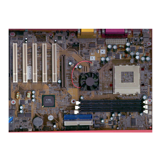
Page 10: Sy-K7Vta Pro Motherboard Layout
Motherboard Description 1-4 SY-K7VTA PRO MOTHERBOARD LAYOUT PS/2 KB PS/2 Mouse Connector Connector USB 1_2 COM1 COM2 GAME LINE-OUT LINE-IN MIC-IN Sigmatel STAC9700 Back Panel ATX Power SDRAM VT8363A SDRAM CDIN1 AGP Slot PCI Slot #1 PCI Slot #2 PCI Slot #3... -
Page 11: Sy-K7Vta Pro Motherboard Components
Motherboard Description 1-5 SY-K7VTA PRO MOTHERBOARD COMPONENTS Sigmatel STAC9700 SDRAM SDRAM SY-K7VTA PRO... -
Page 12: Atx Power Supply Connector
Chassis Cooling Fan Serial Infrared (IrDA) Device Header Front panel connectors Flash BIOS 16-bit ISA Slot 32-bit PCI Mastering Slots Voice Doctor Language Setting Jumper Wake-On-LAN (WOL) Header AC97 Codec Chip AA CD In Connector AB Back panel Connectors SY-K7VTA PRO... -
Page 13: Microprocessor
Motherboard Description SY-K7VTA PRO 1-6 MICROPROCESSOR The motherboard supports a single Socket 462 processor. The processor’s VID pins automatically program the voltage regulator on the motherboard to the required processor voltage. In addition, the front side bus speed (200 MHz ) is automatically selected. The motherboard supports all current Socket 462 processor speeds, voltages, and bus frequencies. -
Page 14: Memory
Programmable I/O drive capability for MA, command, and MD signals Supports PC100 and PC133 SDRAM Two-bank interleaving for 16Mbit SDRAM support Two-bank and four bank interleaving for 64Mbit SDRAM support Independent SDRAM control for each bank SY-K7VTA PRO... - Page 15 Read around write capability for non-stalled CPU read Burst read and write operation BIOS shadow at 16KB increment Decoupled and burst DRAM refresh with staggered RAS timing CAS before RAS or self refresh SY-K7VTA PRO...
-
Page 16: Chipset
Motherboard Description SY-K7VTA PRO 1-8 CHIPSET VT8363A The KT133A chip set consists of the VT8363A system controller (552 pin BGA) and the VT82C686B PCI to ISA bridge (352 pin BGA). The system controller provides superior performance between the CPU, DRAM, AGP bus, and PCI bus with pipelined, burst, and concurrent operation. - Page 17 The USB controller allows hot plug and play and isochronous peripherals to be inserted into the system with universal driver support. The controller also implements legacy keyboard and mouse support so that legacy SY-K7VTA PRO...
- Page 18 One additional steerable interrupt channel is provided to allow plug and play and reconfigurability of onboard peripherals for Windows family compliance. The VT82C686B also enhances the functionality of the standard ISA peripherals. The integrated interrupt controller supports both edge and SY-K7VTA PRO...
-
Page 19: I/O Interface Controller
Infrared-IrDA (HPSIR) and ASK (Amplitude Shift Keyed) IR Multi-mode parallel port Standard mode, ECP and EPP support Plug and play with 192 base IO address, 12 IRQ and 4 DMA options Floppy Disk Controller 16bytes of FIFO SY-K7VTA PRO... -
Page 20: Serial Ports
PC-AT and PS/2 modes. In the Setup program, the diskette drive interface can be configured for the following diskette drive capacities and sizes. 360 KB, 5.25-inch 1.2 MB, 5.25-inch 720 KB, 3.5-inch 1.2 MB. 3.5-inch (driver required) 1.25-1.44 MB, 3.5-inch 2.88 MB, 3.5-inch SY-K7VTA PRO... -
Page 21: Hardware Monitor
Motherboard Description SY-K7VTA PRO 1-9.4 PS/2 Keyboard and Mouse Interface PS/2 keyboard and mouse connectors are located on the back panel of the motherboard. The +5 V lines to keyboard and mouse connectors are protected with a fuse that prevents motherboard components from being damaged when an over-current condition occurs. -
Page 22: Wake On Lan Technology
For Wake on LAN, the 5-V standby line for the power supply must be capable of delivering +5V ±5 % at 720 mA. Failure to provide adequate standby current when implementing Wake on LAN can damage the power supply. SY-K7VTA PRO... -
Page 23: Chapter 2 Hardware Installation
BIOS Setup Utility HARDWARE INSTALLATION Congratulations on your purchase of SY-K7VTA PRO Motherboard. You are about to install and connect your new Motherboard. Note: Do not unpack the Motherboard from its protective anti-static packaging until you have made the following preparations. -
Page 24: Unpacking The Motherboard
BIOS Setup Utility UNPACKING THE MOTHERBOARD When unpacking the Motherboard, check for the following items: The SY-K7VTA PRO KT133A AGP/PCI/ISA Motherboard The Quick Start Guide The Installation CD-ROM SOYO Bonus Pack CD-ROM One IDE Device ATA 66 Flat Cable One Floppy Disk Drive Flat Cable... -
Page 25: Installation Guide
We will now begin the installation of the Motherboard. Please follow the step-by-step procedure designed to lead you to a complete and correct installation. Warning: Turn off the power to the Motherboard, system chassis, and peripheral devices before performing any work on the Motherboard or system. BEGIN THE INSTALLATION SY-K7VTA PRO... -
Page 26: 2-3.1 Cpu Installation
BIOS Setup Utility 2-3.1 CPU Installation Your SY-K7VTA PRO motherboard comes with a CPU retention set kit. The retention set is used to hold the processor attached to the Socket 462 CPU connector on the motherboard. FOC ( Fan-Off Control ) The newly designed SOYO “FOC”... - Page 27 Furthermore, we strongly recommend our users to enable the function of H/W monitoring in the BIOS. This function, together with the FOC, provide the total protection to the CPU and allow it to maximize its performance. them of the correct usage of the K7 CPU. SY-K7VTA PRO...
- Page 28 BIOS Setup Utility Follow these instructions to install your Socket 462 processor correctly. Lift the socket handle up to a vertical position. Align the blunt edge of the CPU with the matching pinhole distinctive edge on the socket. SY-K7VTA PRO...
- Page 29 Then close the socket handle to secure the CPU in place. Remember to connect the CPU Cooling Fan to the appropriate power connector on the Motherboard. The fan is a key component that will ensure system stability. The fan prevents overheating, therefore prolonging the life of your CPU. SY-K7VTA PRO...
-
Page 30: 2-3.2 Sdram Memory Module Installation
CPU front side bus speed. Depending on the DRAM clock speed setting in the BIOS setup (Chapter 3), appropriate memory modules must be used. For 66MHz DRAM speed, use PC66 memory; for 100MHz DRAM speed, use PC100 memory; for 133MHz DRAM speed, use PC133 memory. SY-K7VTA PRO... -
Page 31: Memory Configuration Table
BIOS Setup Utility SY-K7VTA PRO Memory Configuration Table Number of Memory DIMM 1 DIMM 2 DIMM 3 Modules RAM Type SDRAM/VCM SDRAM Memory Module Size 32/64/128/256/512 MB (MB) -
Page 32: 2-3.3 Motherboard Connector
CD-ROM) and plug the other end to the primary (IDE1) or secondary (IDE2) directionally keyed IDE connector on the Motherboard. The ATA66/100 cable is backward compatible with ATA33 HDDs. This Motherboard can support up to four HDDs. ATA 66/100 Flat Cable SY-K7VTA PRO IDE 1 IDE 2 Primary Secondary 40-pin... -
Page 33: Floppy Drive
Connect one side of the 34-pin flat cable to the floppy drive and plug the other end to the floppy drive connector on the Motherboard. This Motherboard can support up to 2 floppy drives. SY-K7VTA PRO Pin -1 Floppy Drive... -
Page 34: Power Led
Plug the computer case's front panel devices to the corresponding headers on the Motherboard. 1. Power LED Please install according to the following pin assignment: pin 1,3 are for Power LED. Speaker Power LED Power LED Pin Assignment SY-K7VTA PRO HDD LED S TR LE D PWRBT Reset... - Page 35 Attach the 2-pin IDE device LED cable to the corresponding IDE LED header on the Motherboard. This will cause the LED to light up when an IDE (HDD, CD-ROM) device is active. HDD LED Pin Assignment Speaker out NC NC SY-K7VTA PRO...
- Page 36 BIOS Setup Utility SY-K7VTA PRO 5. ATX Power On/Off Switch Attach the 2-pin momentary type switch to the PWRBT header for turning On or Off your ATX power supply. PWRBT Pin Assignment Power On/Off 6. STR LED The STR LED is connected to the Voltage that feeds the DIMM sockets.
- Page 37 When connecting an external device, use the following figure to locate and identify which back panel connector to plug the device to. PS/2 KB PS/2 Mouse Connector Connector USB2 USB 1 COM 1 COM2 JOYSTICK LINE-OUT LINE-IN MIC JACK SY-K7VTA PRO SDRAM SDRAM Sigmatel STAC9700...
- Page 38 Motherboard. Pin6 Pin4 Pin2 4. PS/2 Mouse Similarly, plug the mouse jack directly into the 6-pin female PS/2 mouse connector. Pin6 Pin4 Pin2 Pin5 KBD Clock Pin3 Pin1 KBD DATA Pin5 Mouse Clock Pin3 Pin1 Mouse DATA SY-K7VTA PRO...
- Page 39 Attach the joystick cable to the 15-pin JOYSTICK port at the rear panel of you motherboard. This Motherboard features three built-in audio-stereo ports (labeled line-in, line-out, and mic jack) convenient to directly plug-in all your external audio devices. USB3 USB4 (-)Data (+)Data SY-K7VTA PRO...
- Page 40 Wake-On-LAN (WOL) function to the JP10 header on the Motherboard. This WOL function lets users wake up the connected computer through the LAN card. Please install according to the following pin assignment: JP10 Pin Assignment Wake-On-LAN RING 5VSB SY-K7VTA PRO...
- Page 41 BIOS Setup Utility SY-K7VTA PRO 2. Infrared (SIRCON) Plug the 5-pin infrared device cable to the SIRCON header. This will enable the infrared transfer function. This Motherboard meets both the ASKIR and HPSIR specifications. Please install according to the following pin assignment:...
- Page 42 Suspend Mode. (Suspend mode can be enabled from the BIOS Setup Utility, [POWER MANAGEMENT] menu.) To avoid damage to the system, install according to the following pin assignment: CPUFAN Pin Assignment CPUFAN2 Pin Assignment CPU Cooling Fan SENSOR CPU Cooling Fan SY-K7VTA PRO...
- Page 43 ChipFAN connector to provide 12V power to the chassis fan. Connect the cable from the chassis fan to the ChipFAN 3-pin connector. Install according to the following pin assignment: Chipset Cooling Fan ChipFAN Pin Assignment Note: CPUFAN/ChipFAN must be installed for this Motherboard, CHAFAN is optional. SENSOR SY-K7VTA PRO...
- Page 44 Insert the AGP VGA card into the AGP slot. Then connect the monitor information cable to the AGP card back plane external connector. Follow the manufacturer's instructions to perform the AGP VGA drivers installation. CD-IN: CDIN1 Right Left SY-K7VTA PRO...
-
Page 45: Atx Power
The Motherboard requires a power supply with at least 200 Watts and a "power good" signal. Make sure the ATX power supply can take at least 720 mA * load on the 5V Standby lead (5VSB) to meet the standard ATX specification. SY-K7VTA PRO ATX Power... -
Page 46: 2-3.4 Jumper Setting
Refer to the following table to set the Frequency Multiplier of your CPU. Frequency Multiplier Setting Auto Manual Pay special care to the directionality. Short Pin1-2 1 2 3 Short Pin2-3 1 2 3 SY-K7VTA PRO Short Pin1-2 1 2 3 Short Pin2-3 1 2 3... - Page 47 If you set ratio to manual and configure the RJ1 jumper to the settings that match your CPU speed as follow table. Note: SOYO does not guarantee system stability if the user over clocks the system. Any malfunctions due to over-clocking are not covered by the warranty.
-
Page 48: 2-3.5 Voice Doctor
5 seconds to clear the CMOS Note: You must unplug the ATX power cable from the ATX power connector when performing the CMOS Clear operation. SY-K7VTA PRO Chinese Language Short pin 2-3 1 2 3 Retain CMOS Data... -
Page 49: 2-3.7 Power On
Repeat this operation until you get the following screen. 3. The BIOS Setup screen appears: CMOS Setup Utility – Copyright ( C ) 1984-2000 Award Software Soyo Combo Feature Standard CMOS Features Advanced BIOS Features Advanced Chipset Features Integrated Peripherals... -
Page 50: 2-3.8 Quick Bios Setup
This Motherboard does not use any hardware jumpers to set the CPU frequency. Instead, CPU settings are software configurable with the BIOS [SOYO COMBO SETUP]. The [SOYO COMBO SETUP] menu combines the main parameters that you need to configure, all in one menu, for a quick setup in BIOS. -
Page 51: 2-3.9 Troubleshooting At First Start
2-3.9 Troubleshooting at First Start Video (no display) related issues I built a new computer system using a Soyo board and nothing happens when turning it on, no video and no beeps from the PC speaker. What is happening and how can it be fixed? No screen and no beeps mean that your CPU and motherboard do not work at all. - Page 52 5EH_2CA1 (meaning revision 2CA1 for the SY-5EH board) or 6BA+ IV_2AA2 which means SY-6BA+ IV motherboard with 2AA2 bios. Where can I find the latest BIOS of my motherboard? Please go to the technical support page of one of the SOYO websites www.soyo.com.tw (Taiwan: ), and look up your motherboard to find the latest BIOS revision.
-
Page 53: Audio Issues
Why? If you are sure that the modem driver has been installed correctly, then you need to install the south bridge driver from the SOYO CD, this is because Windows does not properly recognize relatively new chipsets. -
Page 54: 2-3.10 Power Off
If you are running a Cyrix CPU, make sure the 'linear burst function' is enabled in the bios. I can not get my board to run properly. Please make sure you have the latest bios and driver from the SOYO web site at: http://www.soyo.com 2-3.10 Power Off... -
Page 55: Chapter 3 Bios Setup Utility
1. Turn on or reboot the system. 2. After the diagnostic checks, press the [Del] key to enter the Award BIOS Setup Utility. CMOS Setup Utility – Copyright ( C ) 1984-2002 Award Software SOYO COMBO Feature Standard CMOS Features Advanced BIOS Features Advanced Chipset Features... - Page 56 Returns at anytime and from any location to the Main Menu. Will display a overlapping window with all options for the current item. Using the +, –, Page Up and Page Down keys the user can toggle the value of the current item. SY-K7VTA PRO...
-
Page 57: Bios Setup Utility
( S h i f t ) F 2 : C h a n g e C o l o r D i s k T y p e … SY-K7VTA PRO Type [Y] to save the changes and exit or [N] to return to the Main Menu and keep current values. -
Page 58: Soyo Combo Setup
<DEL> key during the system diagnostic checks to enter the Award BIOS Setup program. The CMOS SETUP UTILITY will display on screen. Then, select the [SOYO COMBO SETUP] option from the main menu and press the <Enter> key. -
Page 59: L2 Cache Memory
117/39 MHz 120/40 MHz Description This option activates the CPU L2 cache ECC checking function. Description +0.200V This function adjust the CPU +0.225V voltage. +0.250V -0.025V -0.050V -0.075V -0.100V SY-K7VTA PRO Note Default Default Default Note Default Note Default... -
Page 60: Quick Power On Self Test
OnChip Sound Disabled Auto Description Provides a fast POTS at boot-up. Description Select Your Boot Device Priority Select Your Boot Device Priority This item allows you to control the onboard AC 97 audio. SY-K7VTA PRO Note Default Note Default Default... -
Page 61: Standard Cmos Setup
EGA/VGA All Errors 640K 64512K 65536K +/-/PU/PD:Value F10:Save F6:Fail-Safe Defaults Setting Type the current time SY-K7VTA PRO Item Help Menu Level ESC:Exit F1:General Help F7: Optimized Defaults Please Note You can also the PUp/PDn keys to toggle 24-hour clock format... -
Page 62: Floppy Drives
Enhanced IDE hard disk Large IDE hard disk (for certain hard disk) Description Not installed Supports 3-mode floppy diskette: 740KB/1.2MB/ 1.44MB on selected disk drive. SY-K7VTA PRO Note Default Default <528MB >528MB Note Default Default Special disk drive commonly used in... - Page 63 All, But Keyboard All, But Diskette All, But Disk/Key Description Select the video mode. When the BIOS detects system errors, this function will stop the system. Select which type of error will cause the system halt. SY-K7VTA PRO Note Default Default...
-
Page 64: Advanced Bios Features
Advanced BIOS Features Disabled Enabled Enabled Disabled Enabled Fast Disabled Setup Non-OS2 Disabled Enabled Disabled Disabled Disabled Disabled Disabled Disabled +/-/PU/PD:Value F10:Save F6:Fail-Safe Defaults SY-K7VTA PRO Item Help Menu Level ESC:Exit F1:General Help F7: Optimized Defaults... -
Page 65: Virus Warning
Enables the CPU's internal cache. Disabled Enabled Enables the external memory. Description Changes the sequence of A and B drives. Description Seeks disk drives during boot up. Disabling speeds boot up. SY-K7VTA PRO Note Default Note Default Default Note Default Note Default... -
Page 66: Boot Up Numlock Status
12 (Char/sec) 15 (Char/sec) 20 (Char/sec) 24 (Char/sec) 30 (Char/sec) Choose how long after 250 (msec) 500 (msec) you press a key down the 750 (msec) character begins 1000 (msec) repeating. SY-K7VTA PRO Note Default Note Default Note Default Default Default... -
Page 67: Security Option
BIOS Setup program. Description When using an OS2 operating system. When using another, non-OS2 operating system. Enable this field when your HDD supports the S.M.A.R.T. function. Consult your HDD provider for details. SY-K7VTA PRO Note Default Default Default... -
Page 68: Advanced Chipset Features
F5:Previous Values Advanced Chipset Features Disabled 100MHz Disabled Disabled Enabled Enabled Disabled Disabled Disabled Enabled Auto Enabled Disabled Enabled Enabled Enabled Enabled Enabled Disabled Disabled +/-/PU/PD:Value F10:Save F6:Fail-Safe Defaults SY-K7VTA PRO Item Help Menu Level ESC:Exit F1:General Help F7: Optimized Defaults... -
Page 69: Chipset Features Setup
ROM address to this area. If this occurs, select [Enabled] in this field. Disabled/Enabled PCI Master Pipeline Req. This item allows you to enable/disable the PCI to CPU, CPU to PCI concurrency. SY-K7VTA PRO Note Default Default Default Default Default Default... - Page 70 AGP Driving Value in the next selection. This field is recommended to set in Auto for avoiding any error in your system. This item allows you to adjust the AGP driving force. SY-K7VTA PRO Note Default Default Default Default...
- Page 71 When Enabled, every write transaction goes to the write buffer. Burstable transactions then burst on the PCI bus and nonburstable transactions don’t. When Enabled, writes to the PCI bus are executed with zero wait states. SY-K7VTA PRO Note Default Default Default Default Default...
- Page 72 When Enabled, writes to the AGP(Accelerated Graphics Port) are executed with one wait states. When Enabled, read to the AGP (Accelerated Graphics Port) are executed with one wait states. SY-K7VTA PRO Note Default Default Default Default...
-
Page 73: Integrated Peripherals
Auto PCI Slot Enabled Enabled 3F8/IRQ4 2F8/IRQ3 Standard Half No, Yes 378/IRQ7 Normal Epp1.9 Enabled Disabled 220H IRQ 5 DMA 1 Disabled 330-333H Enabled +/-/PU/PD:Value F10:Save F6:Fail-Safe Defaults SY-K7VTA PRO Item Help Menu Level ESC:Exit F1:General Help F7: Optimized Defaults... - Page 74 Auto setting to set the HDD control timing. Disabled Auto Select Auto to enable Ultra DMA Mode support. Choose which card – AGP Display card or PCI VGA card – to initialize first. SY-K7VTA PRO Note Default Default Default Default Note Default...
-
Page 75: Ide Hdd Block Mode
InfraRed interface modes. Choose [Half] or [Duplex] to set UR2 in half duplex mode or full duplex mode respectively. Refer to your IR device specifications to select the suitable mode. SY-K7VTA PRO Note Default Note Default Note Default (port 1) - Page 76 The mode depends on your external device that connects to this port. Choose DMA3 Choose DMA1 EPP 1.9 Select EPP port type 1.9 EPP 1.7 Select EPP port type 1.7 SY-K7VTA PRO Note Default Note Default Default Default Default...
- Page 77 Audio IC uses. Set this item to enabled to make use of MIPI. Select the I/O address for your MIDI functionality. Set this item to enabled to make use of the game port. SY-K7VTA PRO Note Default Default Default Default Default...
-
Page 78: Power Management Setup
Press Enter +/-/PU/PD:Value F10:Save ESC:Exit F6:Fail-Safe Defaults Wake Up Events LPT/COM Disabled Disabled Press Enter +/-/PU/PD:Value F10:Save ESC:Exit F6:Fail-Safe Defaults SY-K7VTA PRO Item Help Menu Level F1:General Help F7: Optimized Defaults Item Help Menu Level F1:General Help F7: Optimized Defaults... - Page 79 Yes gives better power savings. When enabled, this feature allows the VGA adapter to operate in a power saving mode. Selects the method by which the monitor is blanked. SY-K7VTA PRO Note Default power down 15 Min 1 Min...
- Page 80 Description You can set the VGA awakens the system. When On of LPT & COM, any activity from one of the listed system peripheral devices or IRQs wakes up the system. SY-K7VTA PRO Note Default Default Default Note Default Default...
- Page 81 When set to On, any event occurring at will awaken a system which has been powered down. IRQ8 (RTC Alarm), IRQ9(IRQ2 Redir), IRQ10( Reserved), IRQ11(Reserved), IRQ15 (Reserved) IRQ6(Floppy Disk), IRQ7(LPT1), IRQ12(PS/2 Mouse), IRQ13(Coprocessor), IRQ14(HardDsik) SY-K7VTA PRO Note Default Default Default Default Default...
-
Page 82: Pnp/Pci Configuration Setup
PnP/PCI Configurations Disabled Auto (ESCD) Press Enter Press Enter Disabled Enabled Enabled +/-/PU/PD:Value F10:Save F6:Fail-Safe Defaults SY-K7VTA PRO Item Help Menu Level ESC:Exit F1:General Help F7: Optimized Defaults... - Page 83 PCI/ISA PnP card IRQ assignment automatically. DMA-# assigned to PCI/ISA PnP card. Choose IRQ-# and DMA-# assigned to Legacy ISA card. SY-K7VTA PRO Note Default (If there is any doubt, set this field to [No]) Default Recommended IRQ-3,4,5,7,9,10,...
- Page 84 Disabled BIOS will assign IRQ for VGA/USB Enabled Description Integrated Peripherals Interrupt 12 will be released by the PnP BIOS automatically if the PS/2 Mouse Port is not used. VGA/USB port. BIOS won’t assign IRQ for VGA/USB port. SY-K7VTA PRO Note disabled Default Default...
-
Page 85: Pc Health Status
31 º C / 87 º F 5002 RPM 0 RPM 1.60 V 2.44 V 3.30 V 4.80 V 11.94 V Enabled +/-/PU/PD:Value F10:Save F6:Fail-Safe Defaults SY-K7VTA PRO Status ECP/EPP Item Help Menu Level ESC:Exit F1:General Help F7: Optimized Defaults... - Page 86 CPU FAN. The user should also plug the CPU FAN power on the CPU FAN1 pin. The system will auto shutdown if the power is plug in CPU FAN2 pin. SY-K7VTA PRO Note Default...
-
Page 87: Load Fail-Safe Defaults
This option is recommended if you need to reset the system setup and to retrieve the old values. CMOS Setup Utility – Copyright ( C ) 1984-2002 Award Software Soyo Combo Feature Standard CMOS Features Advanced BIOS Features... -
Page 88: Load Optimized Defaults
This option is recommended if you need to reset the system setup and to retrieve the old values. CMOS Setup Utility – Copyright ( C ) 1984-2002 Award Software Soyo Combo Feature Standard CMOS Features Advanced BIOS Features... -
Page 89: Supervisor Password
JP5 to clear the CMOS RAM. All setup information is lost and you must run the BIOS setup program again. Note: If you do not wish to use the password function, press [Enter] directly and the following message appears: Enter Password: Password Disabled!! SY-K7VTA PRO... -
Page 90: User Password
EXIT WITHOUT SAVING After you confirm the password, After you confirm the ↑ ↓ → ← press <Esc> to exit ° (Shift) F2 password, press Time, Date, Hard Disk Type… SY-K7VTA PRO ↔ : Select Item : Change Color to exit... -
Page 91: Ide Hdd Auto Detection
F5:Previous Values Note: This function is only valid for IDE type of hard disk drives. IDE Primary Master Press Enter Auto 0 MB Auto +/-/PU/PD:Value F10:Save F6:Fail-Safe Defaults SY-K7VTA PRO Item Help Menu Level ESC:Exit F1:General Help F7: Optimized Defaults... -
Page 92: Boot Menu
== Select a Boot First device == Boot Menu Floppy Ls120 HDD-0 SCSI CDROM HDD-1 HDD-2 HDD-3 ZIP100 USB-FDD USB-ZIP USB-CDROM USB-HDD SY-K7VTA PRO... -
Page 93: Chapter 4 Driver Installation
DRIVER INSTALLATION Your SY-K7VTA PRO Motherboard comes with a CD-ROM labeled "SOYO CD." The SOYO CD contains the user's manual file for your new Motherboard, the drivers software available for installation, and a database in HTML format with information on SOYO Motherboards and other products. - Page 94 SOYO Motherboard you own and displays the corresponding model name. The user's manual files included on the SOYO CD are in PDF (Postscript Document) format. In order to read a PDF file, the appropriate Acrobat Reader software must be installed in your system.
- Page 95 A description of 4 drivers follows: Bus Master PCI IDE Driver The ATAPI IDE driver enables the performance enhancing bus mastering functions on ATA-capable Hard Disk Drives and ensures IDE device compatibility. (Driver Installation Menu) SY-K7VTA PRO revision:...
- Page 96 Note: Once you have selected a driver, the system will automatically exit the SOYO CD to begin the driver installation program. When the installation is complete, most drivers require to restart your system before they can become active.
- Page 97 Step 4. Check the Latest Releases Click the 'Check the latest Releases' button to go the SOYO Website to automatically find the latest BIOS, manual and driver releases for your motherboard. This button will only work if your computer is connected to the internet through a network or modem connection.
Need help?
Do you have a question about the SY-K7VTA PRO and is the answer not in the manual?
Questions and answers